Click here for more information on this project.
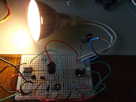
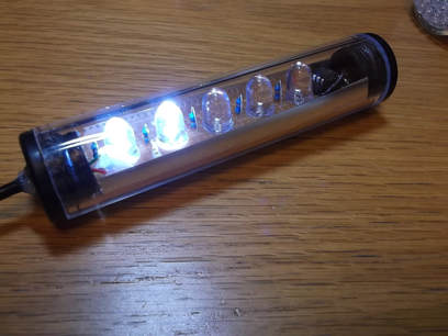
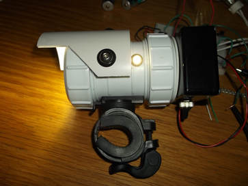
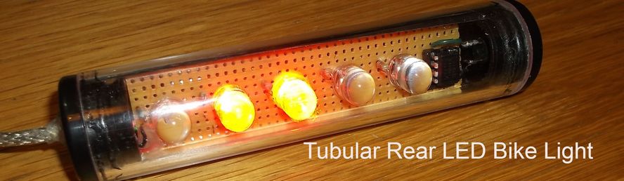
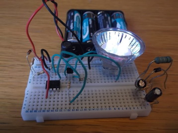
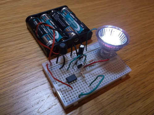
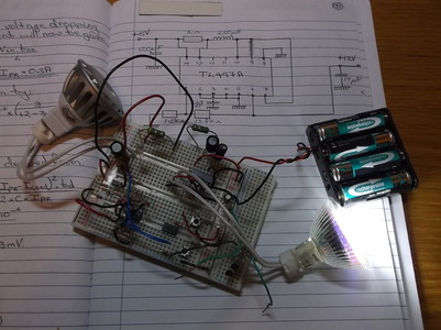
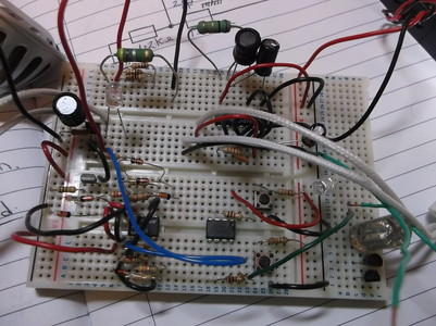
I plan to fit a rear view camera system to my mother's mobility scooter. I needed to supply 24V and 12V to different parts of the system. Rather than use a three terminal regulator which requires considerable heat sinking. i decided to develop a switch mode converter using a PIC 12F675 to drive the converter circuit. This work built on the development of similar step up("Boost") type converters used to drive bike lights using proprietary 12V LED bulbs.
Click here for more information on this project.
2 Comments
While developing the Red LED tubular/bar rear bike light i always had in mind the idea to produce a front version using white LED's. The function of the light would be to allow me or any other rider to be seen rather than to see as 5 LED's of this power can only generate a limited amount of light. The hardware and software used for development were identical to that used for the red version with some additional light patterns added and the LED drive resistor values changed to account for the different white LED forward voltage. Click here to find out more about this project. For a number of years i have used LED lamps to make bike lights. I operated these from 12V Sealed Lead Acid(SLA) batteries. I supplied these to many people but it was not always convenient to use SLA's. I decided to develop a system that would allow the lights to be operated from standard 1.2V rechargeable batteries, allowing users to recharge the batteries on a standard 4 cell charger. The system developed uses a PIC 12F675 micro controller to control the generation of a 12V supply from a 5V battery pack made up of 4 x AA rechargeable batteries. Click here for more information on this project. For a number of years 'bar' type LED rear bike lights have been popular so i decided to implement my own version using 10mm high brightness LED's driven by a PIC 12F675. The software to drive the LED's producing various selectable light patterns was written in C using the Microchip XC8 compiler. For more information on this project click here. I have recently revisited the idea of controlling the current in an LED lamp using a current "chopper" technique. Rather than use discrete devices such as the LM339, LM393 or LM319 i decided to adapt the PIC DC-DC circuit to provide the chopper control function leaving the CPU to provide other functions such as strobe effects and detecting switch inputs to control the strobe effect. Click here for further details of this development. While developing the TL497A DC-DC converter circuit i had in mind the possibility of replacing its functions with a PIC Micro-Controller. After successfully developing the TL497A circuit exactly the same calculations for the component values and design parameters were used to develop a control program for the micro-controller. The micro-controller samples the output voltage and based on the value drives the output stage as required to maintain the 12V output. This project allows a 3.5V-5.5V battery pack to generate a 12V output. The PIC micro-controller can be programmed to generate a system capable of supplying different current outputs. Click here to find out more about this project. Most recently i have been working on a prototype DC-DC converter to alllow 12V equipment to be run from a smaller more easily portable 5V battery pack. A number of people have contacted me asking if i would investigate doing this so that for example bike lights could be run from a smaller battery pack rather than a 12V sealed lead acid battery. Click here for bike lighting projects that i had previously developed. I started this project with a view to proving the concept of running from a lower voltage battery pack while using an industry standard IC such as the Texas Instruments TL497A and then replacing this with a PIC processor such as a 12F675 to generate the pulse stream and carry out the simple logic required to regulate the output voltage. These pictures show just such a prototype on this breadboard driving a 1.6Watt LED lamp. This close up picture shows the evolution of the systems i have developed over the past few months. On the left of the breadboard is the current switch mode system based around an LM393 comparator IC which i have been using for the past few years in various projects. At the top right is the prototype using the TL497 and at the bottom right is the PIC 12F675 which will run the code to drive the components that will replace the internal functions of the TL497A IC. I constructed the circuits on one piece of breadboard to allow their performance to be easily compared driving similar types of loads. I will post more information on this project in the near future. Click here for further information on this project. |
AuthorAllan Faulds is an Electronic Design Engineer who develops Hardware and Software on a professional basis. He has a strong interest in applying his design and development skills to his areas of interest such as bicycle lighting and plant growing and greenhouse and garden control technology. Archives
January 2024
Categories
All
|