Background
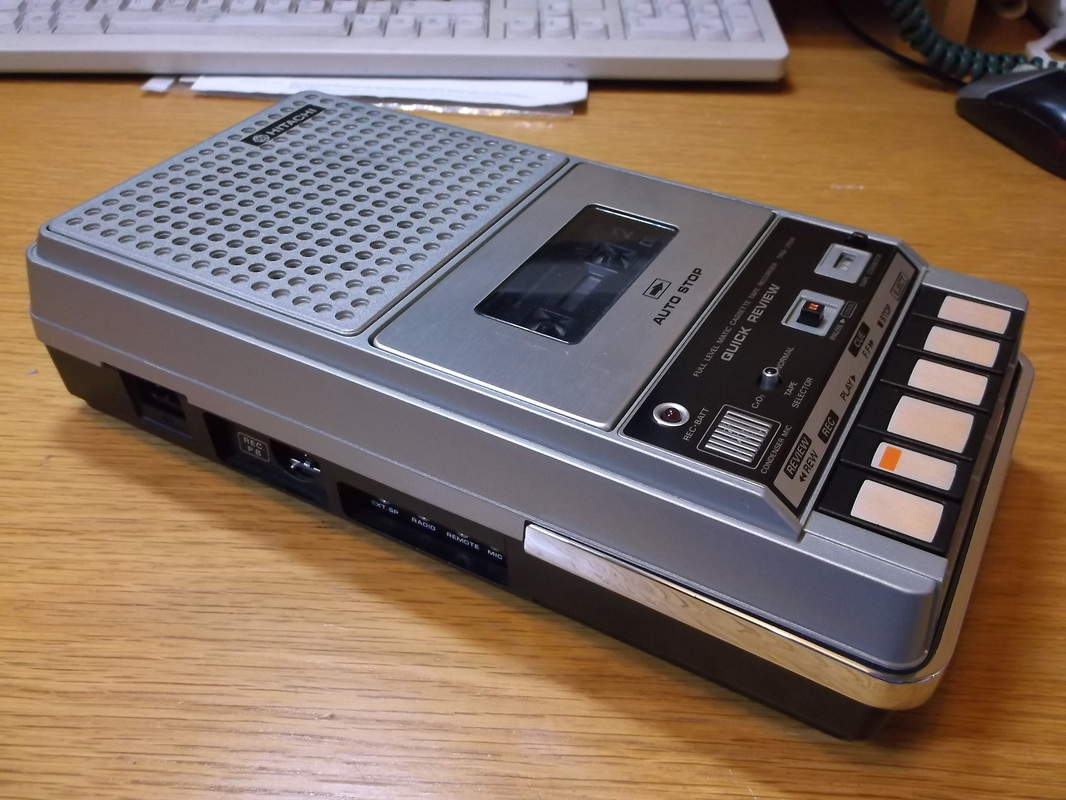
I got this Hitachi cassette recorder(Model: TRQ-295R) as a Christmas present in 1977. It was quite a high end model at the time having a tape counter and Chromium Dioxide selector switch for use with Chrome tapes.
Unfortunately a few months later it developed a fault and would not work from the mains. It would work from batteries or from a mains adapter connected into the battery compartment. All very inconvenient. It went away for repair and worked for about a year then while it was left plugged into the mains for a while it stopped working again. I persevered over the next few years even while using the cassette with the ZX81 computer to save and load programs but eventually gave up on it. It was put into storage in its original box and forgotten about. Occasionally i thought about investigating the problem and trying to fix it but never got round to it.
Recently i was fixing up a ZX81 computer and I/O board and thought it might be interesting to see if the cassette could be used to save and load programs as it had in the past, but only this time without worrying about the state of batteries or having to hook up an AC/DC adapter.
Fortunately the cassette recorder was supplied with a circuit diagram which was quite common during the 1970's for domestic appliances such as this. I knew that the problem was something to do with the mains input circuitry as the cassette worked from batteries and DC power but the circuit diagram will be a great help in diagnosing and fixing the problem.
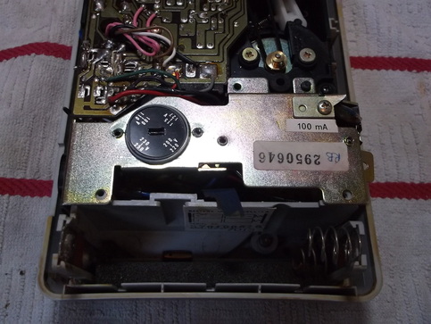
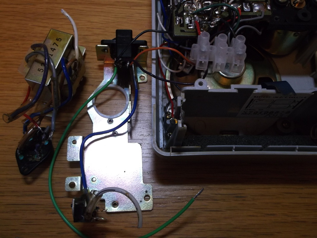
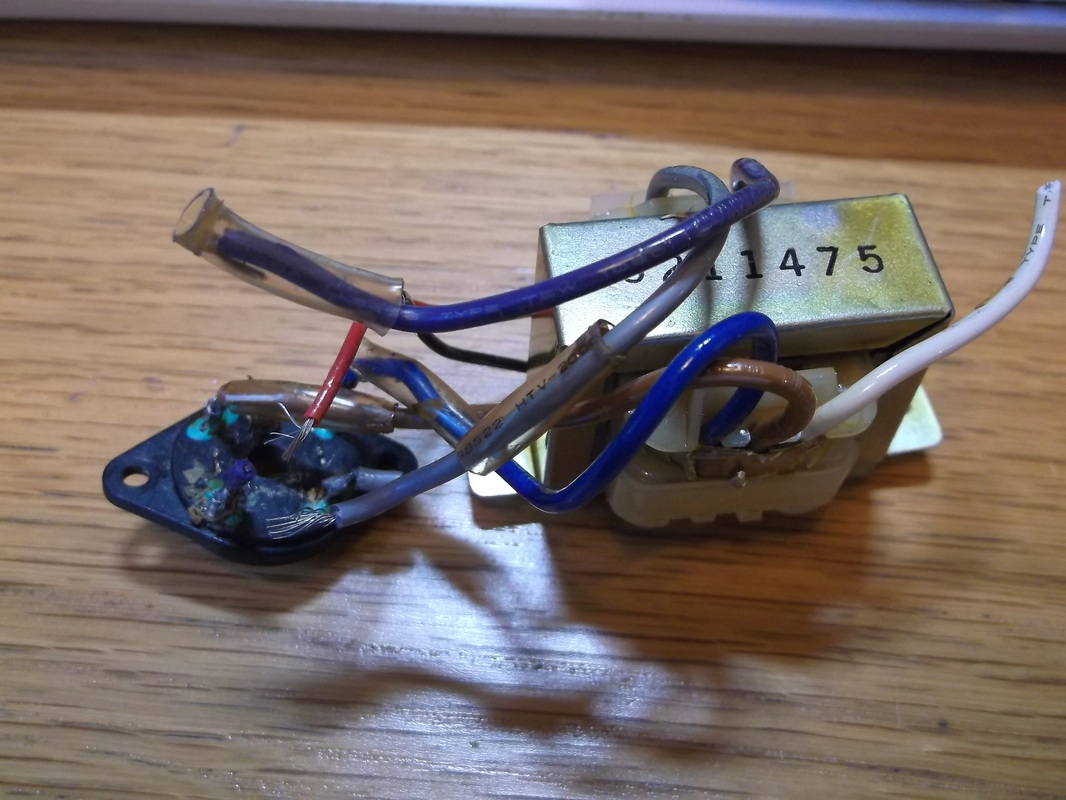
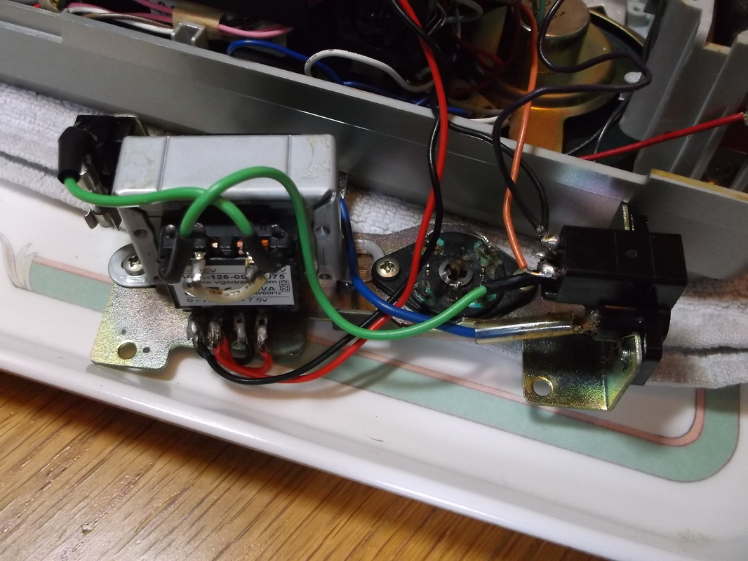
The rotary voltage selector that is part of the problem can be seen in this photograph. The selector switch allows voltage ranges 100-110, 115-127, 200-220, 230-250 Volts to be selected. I assume this was Hitachi's solution to producing one portable model that could be used in all parts of the world. Today rather than producing a transformer with 4 tapping points a universal switch mode power supply would probably be used to solve this problem. The metal bracket supports the mains input socket, the rotary voltage selection switch, the fuse holder and the transformer together with the wiring which connects it all together.
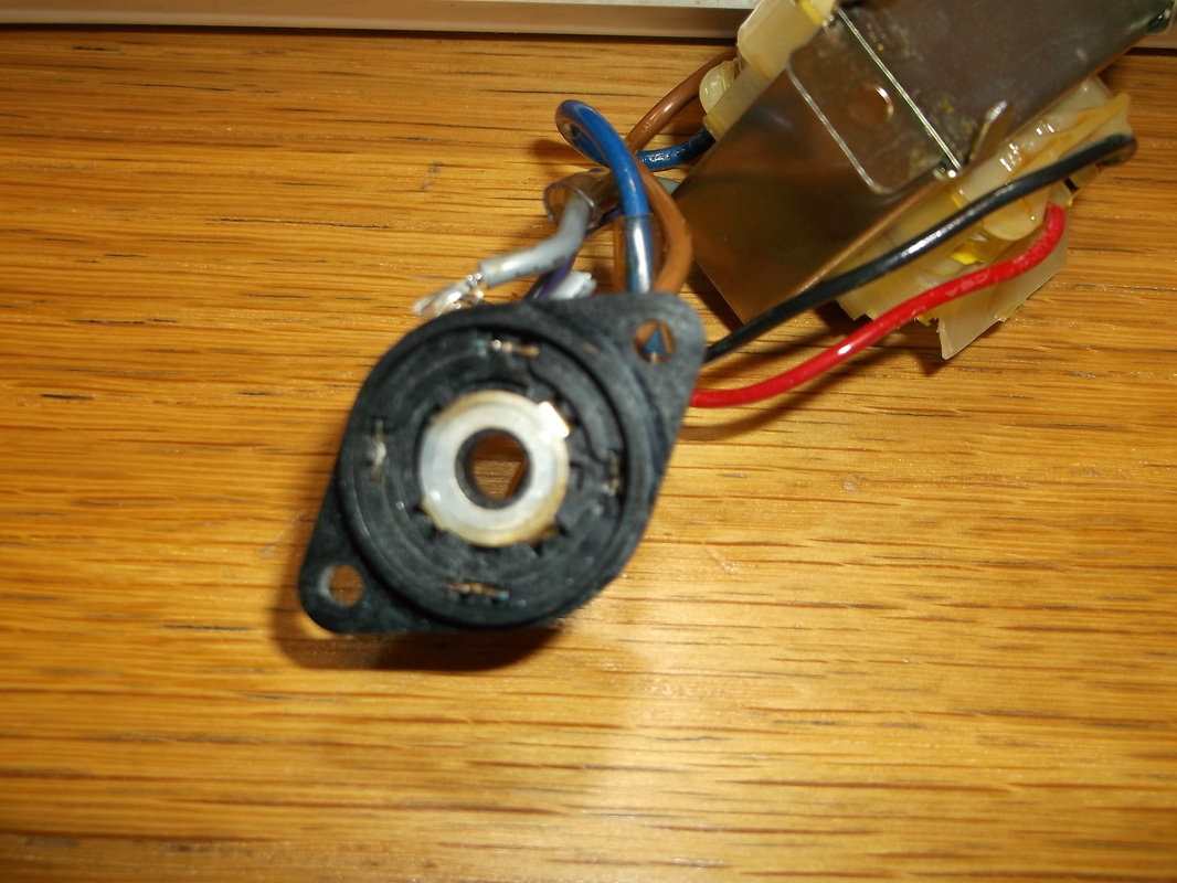
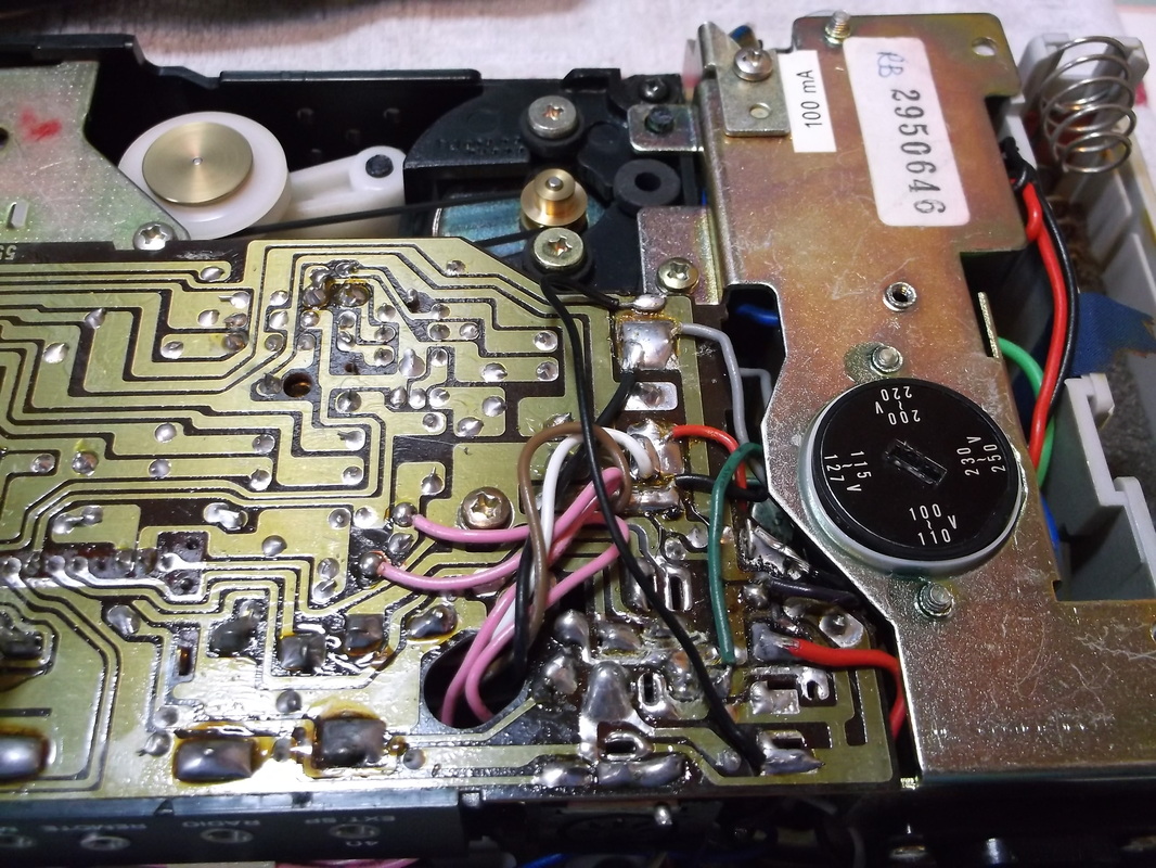
After dismantling the components from the metal bracket the rotary switch was dismantled. This revealed that two of the sets of contacts the 115-127V and 230-250V were damaged and were not sitting in the position they should have been. The continuity check carried out before dismantling showed that the 230-250V switch setting was not working. Since the cassette failed in 1979 the UK mains voltage was dropped from 240V to 230V. I thought i might be able to make use of this as part of some testing.
After diagnosing that the rotary switch and mains transformer were damaged i decided to connect up the cassette to a 6V DC source to verify that the rest of the mechanism and electronics were still working. I was able to play a tape successfully. There was a slight 'wobble' in the audio due to the belts having 'bumps' in them due to being unused for so long and probably because the mechanism was being played upside down. I may have to look at replacing the belts if they do not smooth out with a bit of use.
|
Measuring the resistance between the different connections on the mains tapping wires revealed that the 230-250V connection was open circuit, however the 200-220V was still conducting. The resistance readings from the lower voltage windings did not seem consistent with readings for the higher voltage windings which was a concern. The transformer was removed from the metal plate, the 200-220V connection was wired to the mains,(rather than the non functioning 230-250V one) a 160mA fuse installed and a multimeter connected to measure the output. The fuse blew immediately with no load connected to the output. I suspect that there is a short circuit in the primary windings of the transformer.
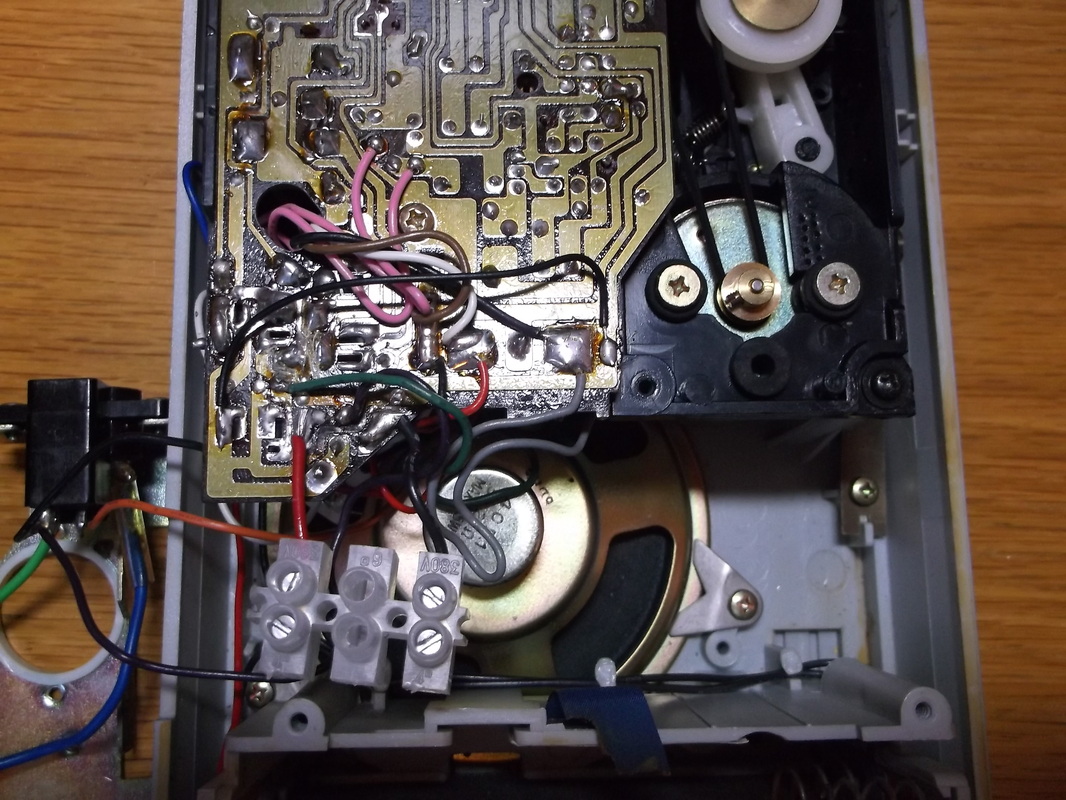
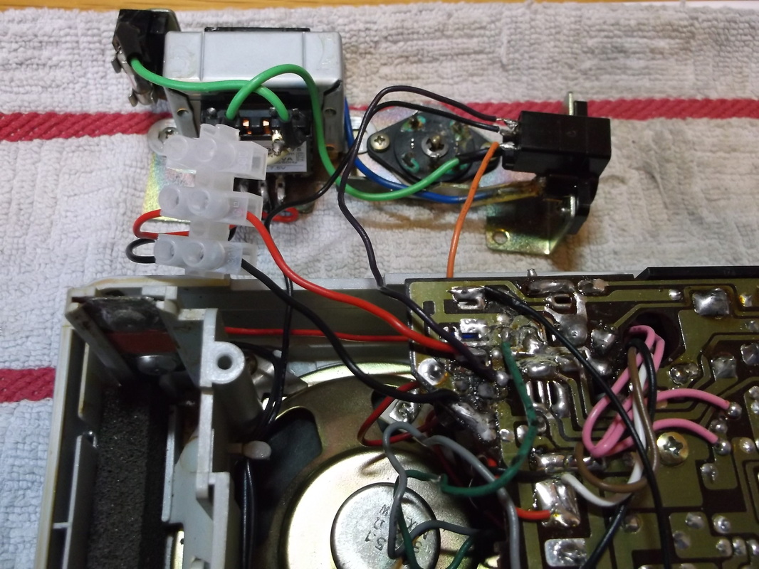
The terminal block in the foreground was used to connect a 6V battery to test the mechanics and electronics of the cassette.
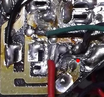
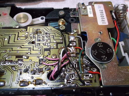
When i dismantled the cassette i was aware that when it was repaired in 1978 the quality of the soldering was not great. There were a lot of large blobs of solder where too much had been used to reconnect wires. There was also a lot of rather strange brown glue/'goo' spread over the contacts of the rotary switch. This lead to a problem during testing where my hand may have pushed down on one of the wires causing a short circuit between two tracks There was a puff of smoke and everything stopped working! |
Damaged PCB track and bridging repair wire(left of picture).
|
Transformer mounted in cassette and repair wire on PCB(Black wire).
|
|
I immediately started sniffing around for the unmistakeable smell of scorched electronic components but could not find any. This was a little encouraging! After a few moments i found a track next to the positive supply line which was dis-colored, De-laminated from the board and broken. The area above the red dot in this picture shows the track break. I traced the track and then fitted a wire to bridge the break. The black wire at the left of the picture shows one end of the repair. I also de-soldered the positive supply, de-soldered the pad and re-soldered it.
|
The black wire running from one side of the PCB to the other is the repair wire which bridges the sections that were connected by the burnt out track.
|
After the repairs were carried out the drive was again connected to the 6V battery and a tape was successfully played. Using the Internet I searched for a suitable replacement transformer and found one available from Maplin. I placed an order and expect it to be delivered in the next few days. It will not have the voltage tap points the original has but i will work around that and after all i do not intend taking the cassette to any foreign countries! More to follow.......
Update 30th March 2015
The replacement transformer was delivered a few days ago and i got time to start work on installing and testing it today.
The replacement transformer was delivered a few days ago and i got time to start work on installing and testing it today.
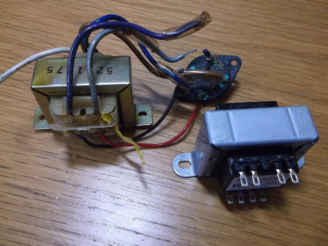
Old and new transformers side by side for comparison.
This picture shows the replacement transformer beside the original one. The new transformer has two primary windings of 115V and two secondary windings of 7.5V. These will need to be wired to operate from 230V and produce a single output of 7.5V.
|
New transformer wired and attached to mounting plate.
The transformer was wired up and attached to the mounting plate. The old wires and clear insulation/sleeving was removed and replaced with new wire and heat shrink sleeving. It would have been preferable to keep the old wiring but it had been soldered a few times in the past and had become quite stiff and brittle at the ends.
|
The new transformer was bench tested outside of the the cassette to verify that it was all working as expected.
The transformer mounting bracket was then installed into the cassette. Some adjustment of the routing of the wires was required to allow for good clearance, avoid rubbing of wires against other components and to allow the covers to be refitted without crushing any of the wires.
The covers were then test fitted to ensure that they would fit. The mains connector was inserted and the cassette was tested. The motor turned in forward and reverse. A tape was inserted and this played successfully. The audio quality was not great but that was due to the unit being operated upside down. The unit was turned the correct way up and the audio was then as expected.
The tape was run for a few minutes and the voltages checked. At this point i noticed that the mounting plate was warmer than i expected. I also noticed that the area where the wires from the transformer were soldered to the PCB was very warm as were the connecting wires themselves. I removed the transformer and mounting plate from the cassette and found the transformer was very warm although it had only been run for less than 10 minutes. I left the cassette plugged into the mains without playing a tape and the transformer continued to get hotter as did the same area of the PCB. There is clearly some sort of problem and a high current is being drawn from the PSU even when the cassette is sitting idle. I will need to investigate this problem further. More news to follow soon....
Update 1st April 2015 : I spent a bit of time checking all the wiring and tracing it against the circuit diagram. It was clear that the problem was within the AC area of the system. As the mains transformer had been replaced this left only the wiring and the bridge rectifier on the PCB at fault. The wiring all checked out with the circuit diagram. After an hour or so i came up with a theory as to how the bridge rectifier could have partially failed, still allow the cassette to operate and develop a great deal of heat while sitting idle but connected to the mains. See below for more details.
I decided to remove the vertically mounted diode modules and replace them with a modern bridge rectifier module and see if this solved the problem. I selected a small 1.5Amp module as this would be more than enough for the cassette.
|
|
|
This photograph shows the circuit board removed from the chassis and the new bridge rectifier module soldered into place on the PCB. The bridge rectifier module is the small black circular module at the centre of the photograph at the immediate right of the grey wire. A great deal of care was taken to remove the old diodes to avoid excessive heat damaging the PCB tracks. As the glass bodied diodes were removed at least one was already broken as it came away in two pieces...both good and bad news! See the failure analysis later on this page.
This is the cassette fully re-assembled complete with the retractable chrome carrying handle.
|
The PCB was reinstalled in the chassis for testing before the cassette was fully reassembled. The terminal block was used to allow easy connection and disconnection in the event any problems occurred. The mains was connected and left for several minutes. There was no heating of the PCB in the bridge rectifier area nor in the transformer as there had been with the old diodes. The voltages were checked and all were normal. A tape was installed after the forward and reverse functions were tested and this played successfully. The tape was played for 10 minutes and there was no excessive heating as previously occurred. So the problems have now been resolved and the cassette is working normally.
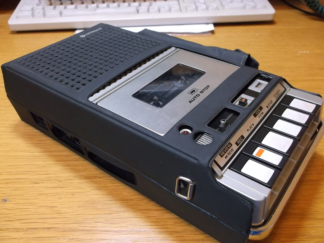
This is the cassette in its carrying case. The pocket on the far side has the clip on carrying handle and the ear phone(mono!) for private listening.
|
Failure Analysis
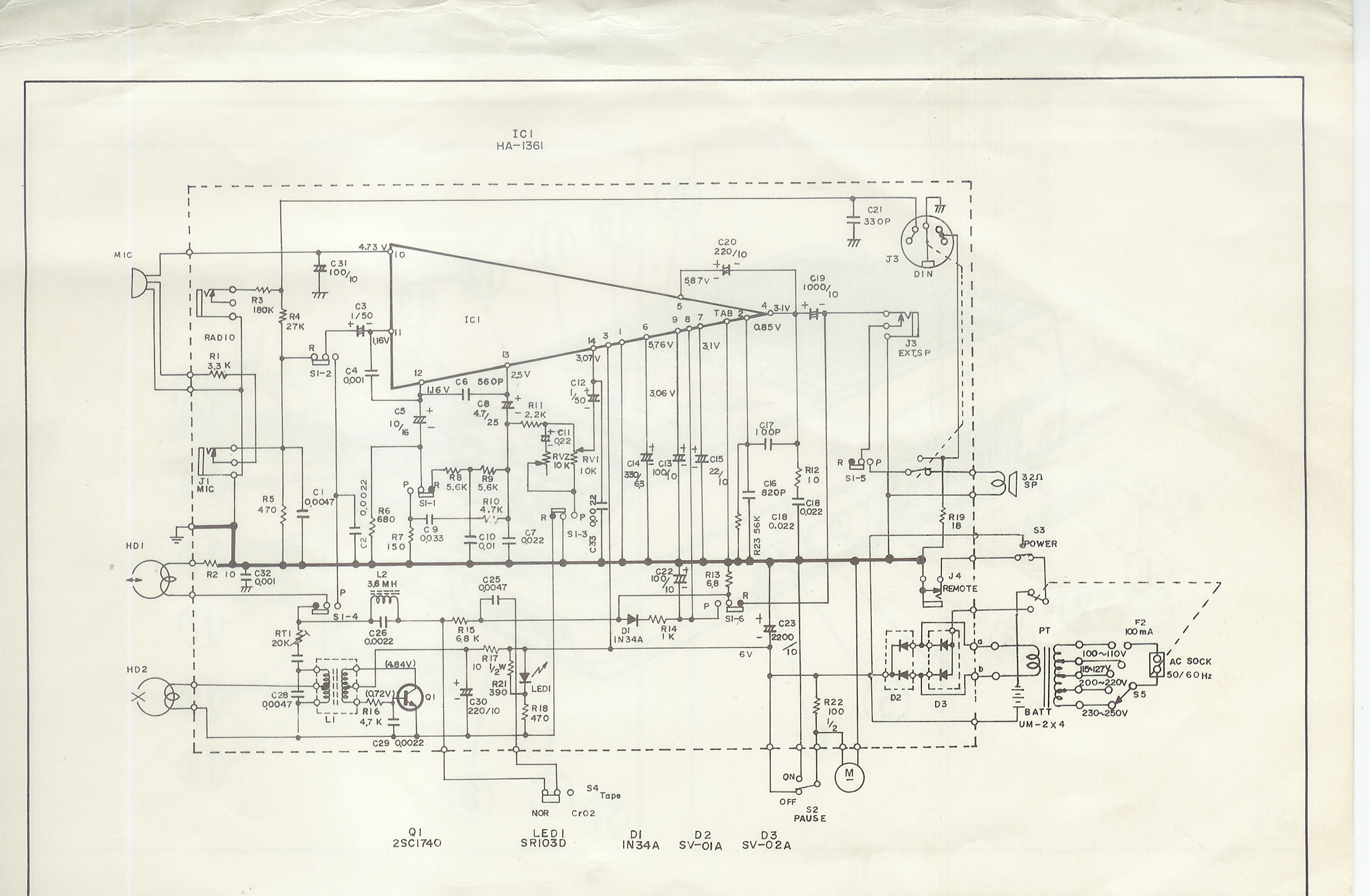 Hitachi TRQ295R Cassette Recorder Circuit Diagram. (Click picture to open a larger version.)
The circuit diagram showed that the bridge rectifier was formed not from four discrete diodes but from 2 diode pair modules.
Research on the internet revealed that theses appear to be Hitachi specific components, although i have seen diode pair modules such as these before. The diode modules were De-soldered and the mounting holes cleared of solder.
Fortunately the original mounting holes for the diodes allowed the four pins of the bridge rectifier module to be easily mounted and soldered in place.
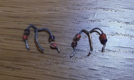 Original glass diode modules removed from PCB.
This picture shows the diode modules after they were removed from the circuit board. While removing these at least one was already broken and came away in two parts.
Mounting components vertically like this is always a little risky as during the wave soldering process the heat is transferred directly into the body of the component. When the components are mounted horizontally the leads at each end of the component act as heat sinks reducing the amount of heat transmitted to the body of the component.
I suspect that the diodes were damaged when the cassette recorder was originally manufactured. In the same way as i experienced, the fault was not found at the final factory test inspection because the cassette would work for the few minutes the test would take with the transformer only failing after being connected to the mains for several hours and the heat building up internally until the windings fail.
I suspect that one or more of the diodes was not working as a diode should, but more like a cross between a zenner diode and resistor. When these diodes should not be conducting during the AC mains cycle they were in fact conducting causing the circuit to operate in more of a half wave rectifier mode rather than full wave rectifier mode. When the diodes were not supposed to be conducting they in fact were and as a result were dissipating a large amount of power causing the heating of the circuit board and surrounding areas. Fortunately the very generous areas of copper on the PCB around these components helped to dissipate the heat and stopped the copper foil delaminating from the board. The fact that the transformer was also mounted on a large metal bracket also helped spread the heat and allow it to survive much longer than it otherwise would.
Although the cassette recorder is considered obsolete technology it was still very satisfying getting it to work as it originally should have. Now i need to dig out all those tapes i have in storage and give then a try and connect it up to the ZX81 computer and load some of those old programs.
