Background
I wanted to fill in the underside of the decking with something different to the vertical strips that seems to be fairly universal on the other caravans. Because the sub-structure is very 'minimal' and tidy i considered simply leaving the underside open as i quite enjoyed seeing the structure but i also wanted to include some storage under the decking so the decision was made that some kind of enclosure would be needed.
I came across this heavy duty trellising in a DIY/Garden centre and decided to use that. It was available as 2400mm x 610mm panels. I was able to transport these to the caravan in the car in two batches as they were not available for delivery from the local branch.
I came across this heavy duty trellising in a DIY/Garden centre and decided to use that. It was available as 2400mm x 610mm panels. I was able to transport these to the caravan in the car in two batches as they were not available for delivery from the local branch.
The first job was to try to arrange the panels in such a way as to make the most efficient use of them with the minimal cutting. I also planned to make the panels easily removable for inspection and maintenance of the underside of the decking so the panels were cut to match up with the decking legs wherever possible.
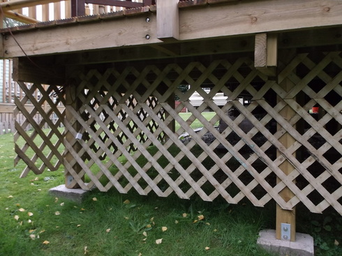
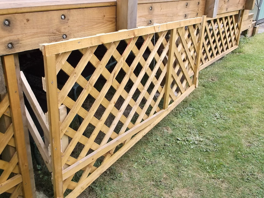
This photograph shows the panels tacked in place while trying to make the best use of the them to cover the open areas.
Once the panels were tacked in place the excess length was cut away to the appropriate length and the framing strips were secured to the trellising using stainless steel screws.
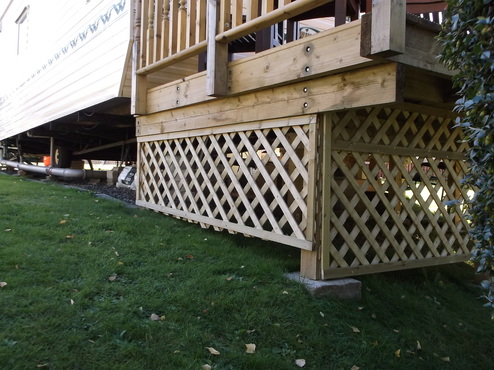
Sufficient gaps were left under the panels to allow the grass to be cut with a petrol grass strimmer without hitting and damaging the trellis panels. In this photograph the excess shown below the left side panel was sawn off so that it would not snag the nylon line of the strimmer.
The same construction process was repeated around the decking base.
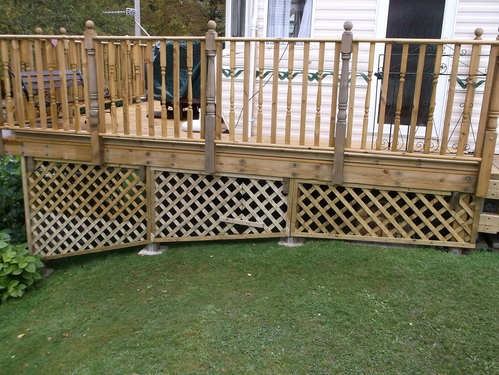
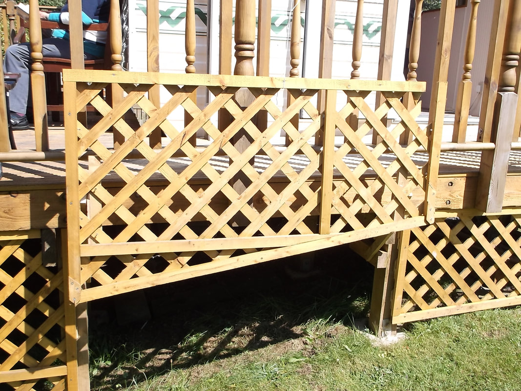
Where required sections of trellis were joined to make a complete panel. In this photograph two sections are being held together temporarily while the framing position is finalised.
Some additional stiffening and framing was added after these photographs were taken to hide join lines.
Decking oil was applied to help protect the wood. Additional coats will be applied when required to maintain the trellis.
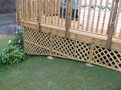
This picture shows the final framing of this section of the trellising.
Each section of trellising is attached to the decking legs with four fixings to allow easy access to the underside.
In 2016 i hope to add a lifting mechanism that will allow some of the panels to be lifted so that the space beneath the decking can be used for storage. I have already designed the lifting mechanism and have produced a small prototype using Meccano. I plan to construct a full size prototype over the winter of 2015/2016 and install it next year
Update May 2017 : Trellis Lifting Mechanism.
After a longer delay than i had anticipated i got started on the lifting mechanism to allow access to the underside of the decking. Currently the trellis panels are secured in place with screws. One panel will have an easy lift mechanism that will allow access to the underside for storage, cleaning, maintenance and inspection.
I decided on a vertical opening as opposed to a side hinged one as with the latter if the closing/securing mechanism were to fail the large panel would flap in the wind possibly coming loose causing damage to itself, the decking and surrounding property.
I decided on a vertical opening as opposed to a side hinged one as with the latter if the closing/securing mechanism were to fail the large panel would flap in the wind possibly coming loose causing damage to itself, the decking and surrounding property.
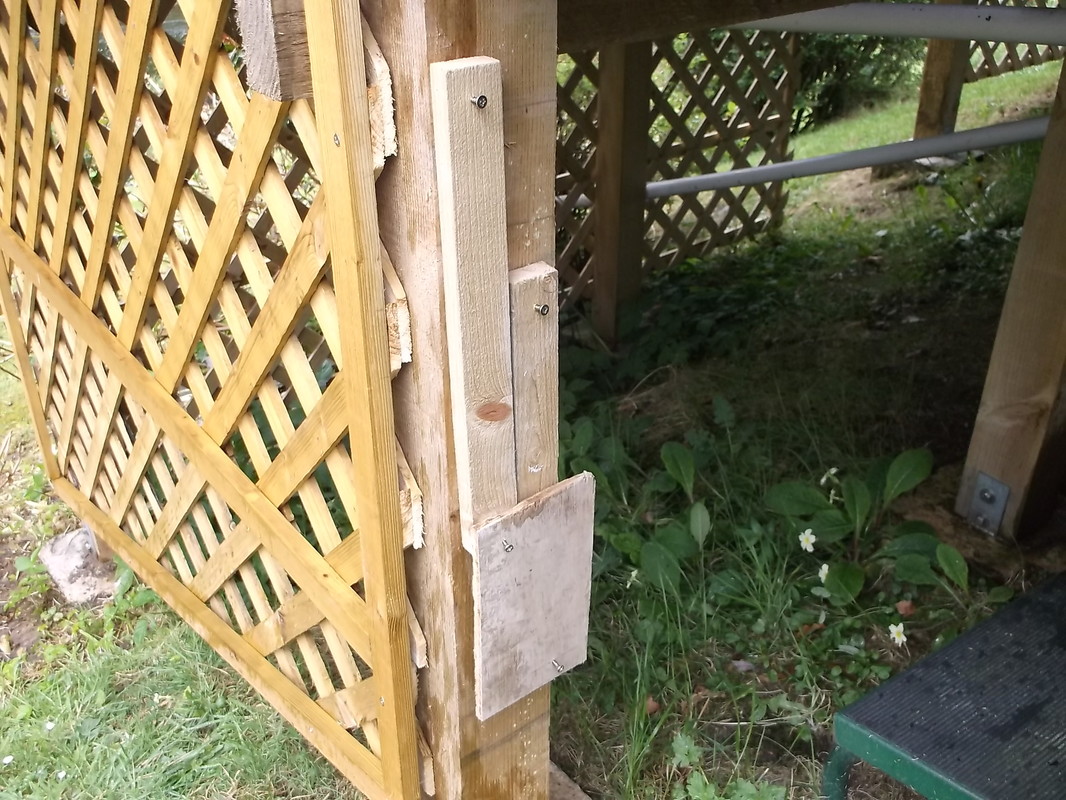
Prototype lifting mechanism in the closed position.
|
Prototype lifting mechanism in the partly open position.
|
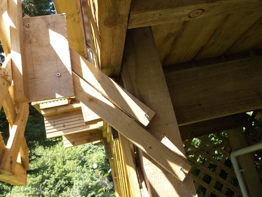
Prototype lifting mechanism in the fully open position.
|
The above pictures show the prototype lifting mechanism installed for testing. The basic geometry had been designed and the initial paper calculations completed. The prototype was constructed from off cuts of wood left over from the construction of the decking. A miniature version had been constructed using Meccano some time ago.
After verifying that the calculated dimensions worked with the prototype lifting brackets the next step was to attach the trellis panel to the brackets and verify that the panel would sit against the decking correctly and that the panel could be lifted easily and clear the decking.
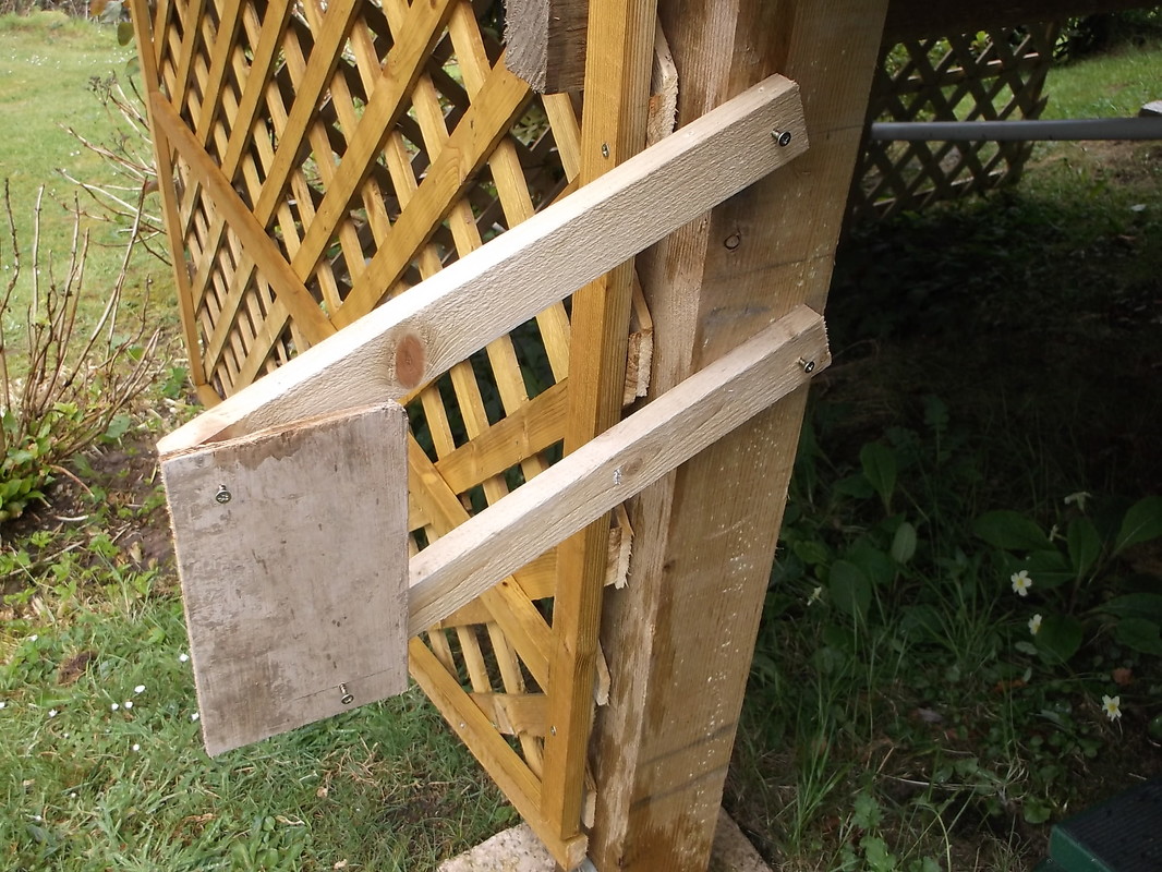
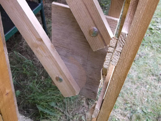
The trellis panel was attached to the lifting bracket plate with wooden battens on the rear side of the panel. The battens were srewed to the trellis panel and to the lifting bracket plate
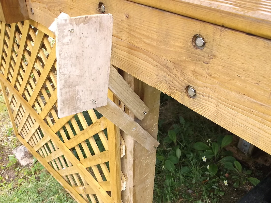
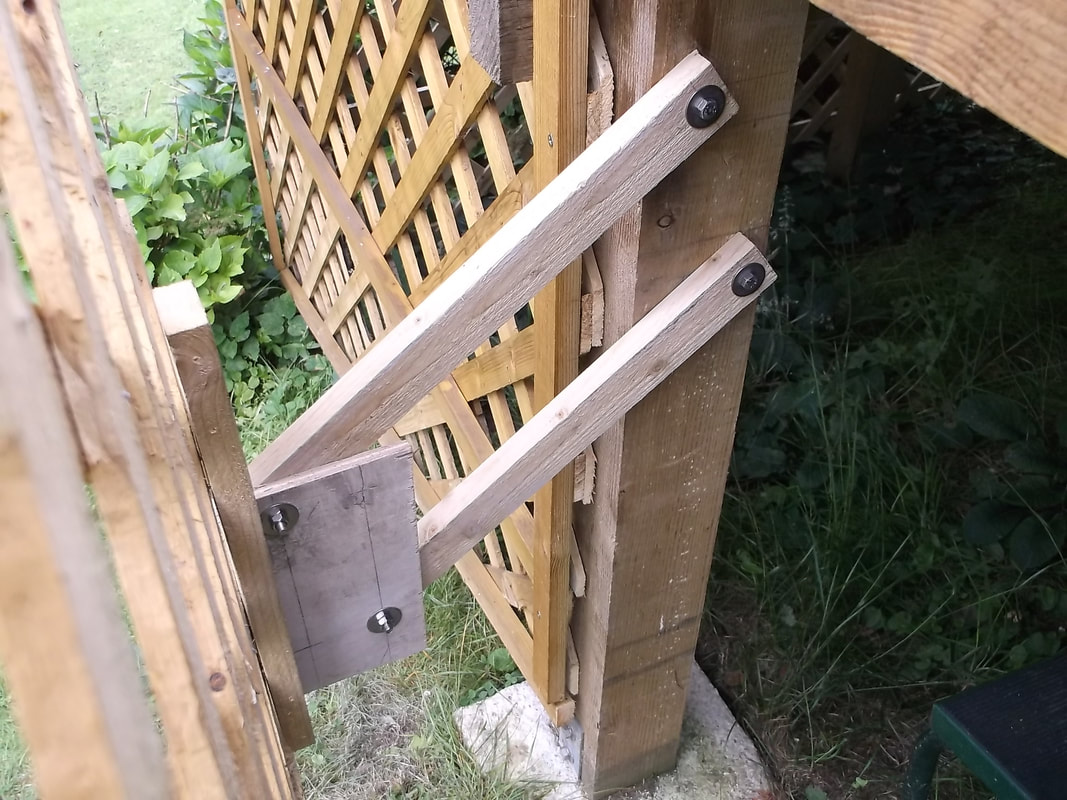
In this picture the pivot points are temporarily implemented with screws.
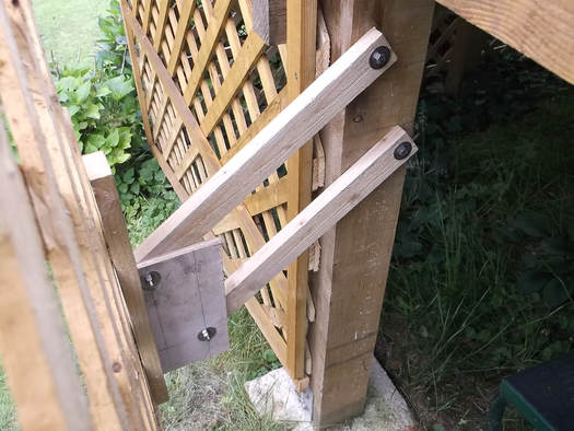
After the prototype was constructed and the mechanism proven to work correctly the temporary screws were replaced with stainless steel coach screws and washers securing the lifting levers to the decking frame and coach bolts, washers and nuts securing the lifting bracket to the lifting levers.
This picture shows the lifting mechanism on the rear of the trellis panel.
This picture shows the outside edge of the lifting lever bracket.
Stainless steel coach bolts with smooth low profile heads were used to allow the mechanism to slugly slide into the decking frame opening.
The plywood used to make the bracket plates were treated with PVA glue solution to protect the wood from water, paying particular attention to sealing the edges.
Trellis panel just opening clearing the handrail post.
|
Trellis panel in fully open position.
|
Trellis panel partially open showing lifting mechanism.
|
