Background : PIC 12F675 Driven 12V/1.6W LED Lamp
Since developing a step up voltage converter/inverter system using the PIC12F675 Micro controller i have decided to convert the 12V LED lamp bike lights to run from 5V battery packs made up from 1.2V rechargeable batteries. This will decrease the battery capacity however it will also reduce the bulk and weight. Using only 4 batteries also means that they can be recharged on a standard 4 unit battery charger.
The bike light uses a standard 12V/1.6W LED bulb driven from a step up voltage converter that steps up the 5V to the 12V required to drive the LED. The driver circuit is based around the PIC 12F675 microprocessor and software developed in another project for items like this. The hardware and software emulate the operation of the Texas Instruments TL497 switch mode power supply chip in the step up mode. The software developed to drive the converter circuit was written in a mixture of 'C' and assembler developed using the Microchip MPLABX IDE tool. Assembly language was used to generate accurate times for the pulse width generation part of the circuit.
The LED lamp and side facing LED's are housed in the original white plastic plumbing fixture modified with a cowl to help direct the light. The drive circuit and switch are mounted in a plastic case which is fixed to the rear of the LED lamp housing.
The light is powered from a 5V supply available via a USB plug so it can be powered from suitably modified battery pack with a USB socket fitted. The lamp can be used as a general purpose torch in the car or house as it can also be powered from a battery power bank,car USB socket, laptop USB socket in fact any USB power source.
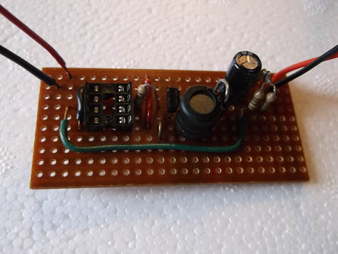
This is the PIC 12F675 micro controller circuit board constructed with components designed to drive up to 3W loads with a 12V output.
The circuit could have been made smaller by reducing the component spacing however as a first attempt i decided to be generous with the spacing to make any debugging that may be required as easy as possible.
The programmed PIC 12F675 has not yet been installed.
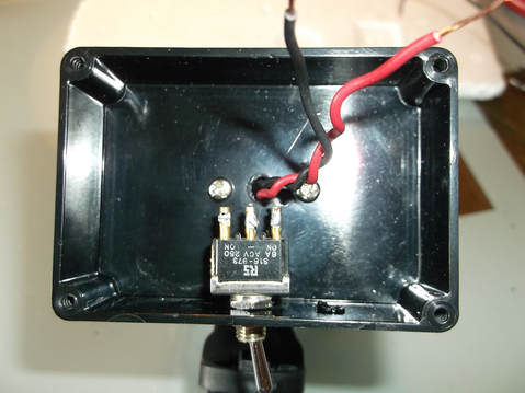
The black plastic box that was to hand was ideal for housing the drive circuit and the on/off switch. The on/off switch was originally mounted on the LED lamp housing.
Holes were drilled in the plastic box to allow the LED cables to be connected to the drive circuit and for mounting holes for the on off switch and securing screws.
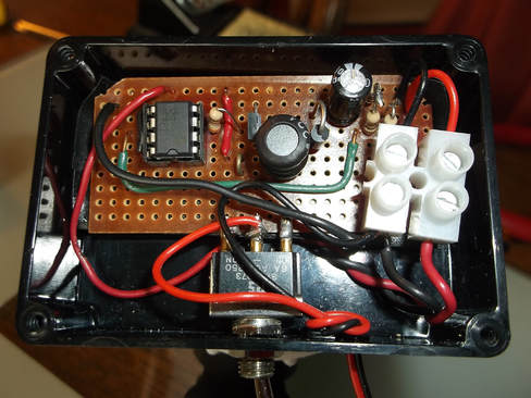
In this picture the driver circuit board has been mounted in the box and connected to the on/off switch, the power supply cables and the LED Lamp.
The PIC 12F675 micro controller was programmed and bench tested before being installed in the driver board.
This picture shows the driver circuit box closed up and the water proof cover of the switch installed on the underside of the box.
The cable was terminated with a USB connector. The battery packs used to power the lamps will be modified to use a mating USB connector.
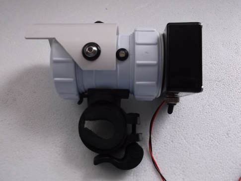
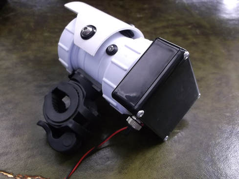
This picture shows the fully assembled LED lamp with the driver circuit box mounted on the rear of the housing.
The cowl was added some time ago to help direct the light and to avoid dazzling drivers coming in the opposite direction.
The handle bar mounting was purchased on line and bolted to the LED lamp housing.
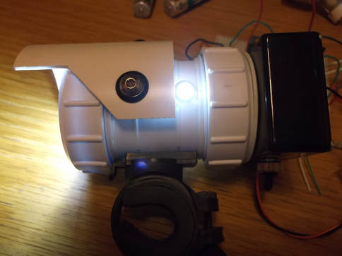
The LED LAMP was bench tested for several hours. Here the side looking LED's can be seen.
These serve two purposes:
1. They allow on coming drivers to see me when i am at a junction and about to turn.
2. They attract the attention(hopefully) of drivers and passengers of slow moving vehicles when i am moving through traffic alerting them to my presence so they do not hit me if they decide to change lane suddenly.
