Background
I purchased this set of dual tone air horns around 1984/1985 for a car i had at the time. I never got round to fitting them so they were safely packed away and stored in the shed over the past 32-33 years. I thought i would test them to see if they were still working with a view to selling them to someone who wanted a retro or vintage set of air horns for a 1970's or 1980's car restoration project.
I had a spare 12V car battery lying around so i was able to use this to test the air horns. Before testing the compressor on the battery i decided to strip it down in case it was seized and attempting to operate it would simply damage the compressor parts and the drive motor itself.
All the components including the electrical relay were made in Italy. Today these type of devices are all manufactured in China or other low labour cost Asian countries.
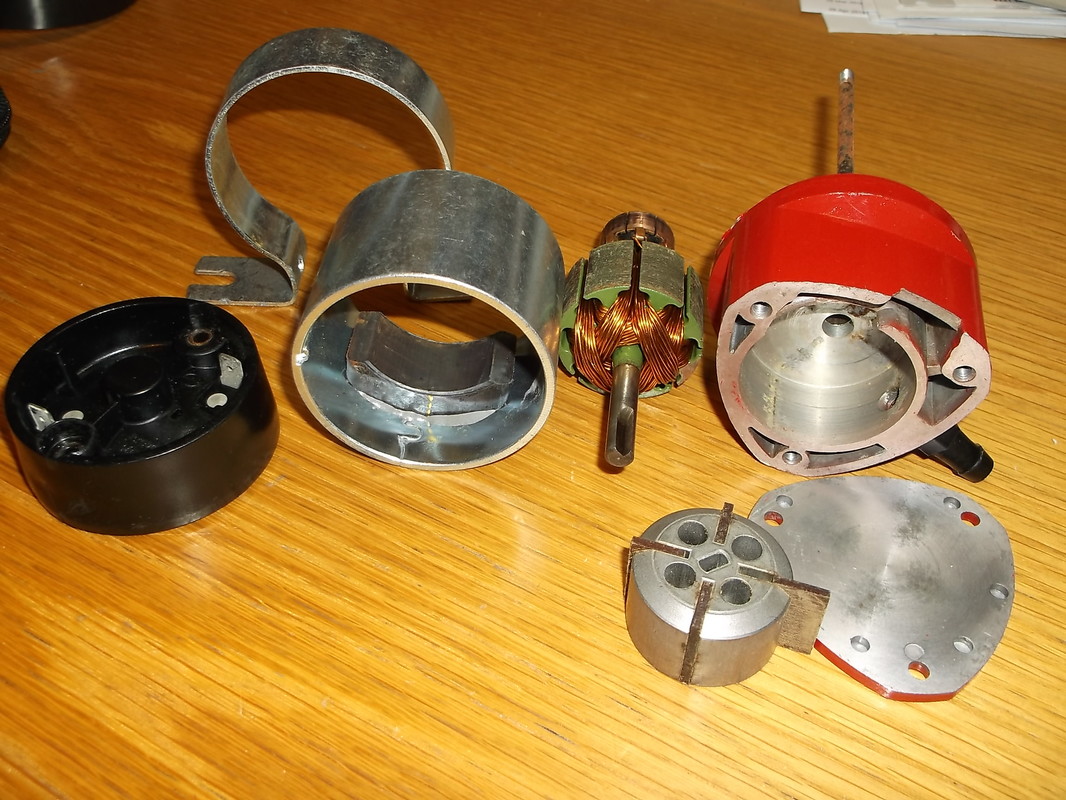
The first job was to disassemble the compressor to examine the parts for any damage or deterioration that may have occurred due to being in storage for so long. This picture shows the unit dismantled showing all the component parts.
|
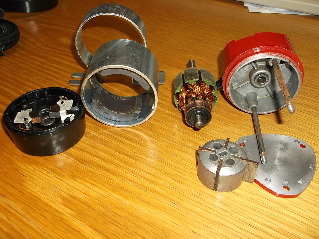
This picture shows the same parts from the reverse view. As the unit has never been used other than to test it when it was originally purchased they were mostly in very good condition.
|
The motor brushes and housing were in very good condition and showed no signs of damage . The permanent magnet housing was in very good condition and only required a wipe down to remove some dust. The rotor, winding's and commutator were all in good condition however the bearing grease had dried out. The compressor housing was generally in good condition however the rotor vanes had seized and left some markings and debris on its surface. The compressor rotor and the vanes had dried out leaving marks on the compressor housing and the end plate. The compressor end plate had markings from the rotor not moving for so many years.
The following work was carried out as part of the refurbishment:
1. The motor brush housing bearing was greased.
2. The rotor bearings were cleaned and greased.
3. The compressor housing bearing was cleaned and greased.
4. The compressor rotor and vanes were cleaned and lightly oiled. The vanes were in very good condition.
5. The compressor housing and end plate were cleaned with soap and wire wool to remove the dried out lubricant and dust.
All the components were allowed to thoroughly dry before being reassembled.
After cleaning up all the components reassembly started. There were spurs on the housing components which ensured that the various components would be oriented and aligned correctly.
The vanes of the compressor rotor were covered with a generous coating of machine oil.
I have refurbished a number of permanent magnet DC motors over the years and the most frustrating part is always trying to get the rotor back into the magnet housing without the partially assembled bits coming apart due to the effects of the magnet. If this occurs it often results in bearing grease being spread all over the inside of the motor which then has to be removed before the next attempt to reassemble the motor!
Fortunately i have developed a number of simple fixes to overcome this and always do a number of 'dry runs' before the final attempt.
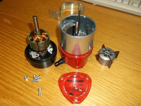
Here the motor and compressor are mostly assembled and only the compressor rotor and the end plate are still to be refitted.
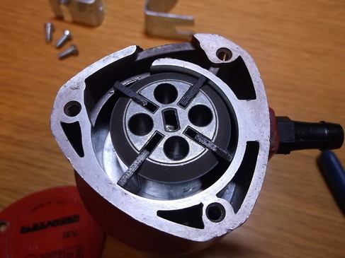
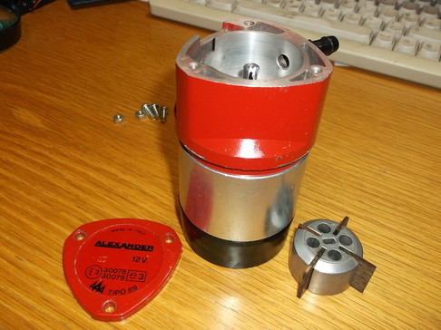
This picture shows the compressor with the rotor and vanes installed. The compressor housing was oiled before the rotor was installed.
The compressor works by sucking in air through the vent at the top of the picture. The vanes are able to move in and out the slots due to the rotation of the rotor generating centripetal force. As the rotor rotates the air sucked in via the vent gets trapped between two of the vanes and is then compressed as the rotor continues to rotate. When the leading vane reaches the '3 o'clock' position the compressed air starts to escape through the black vent on the right of the picture and out to the air horns via the plastic tubing. The whole process repeats as the rotor rotates. I suppose it could be described as 'suck, squeeze, blow, hoot' in the same way as the 4 stroke internal combustion engine is described as being ' suck, squeeze, bang, blow' ! The compressor housing and rotor actually looks a bit like a Wankel/Rotary engine in cross section.
The compressor works by sucking in air through the vent at the top of the picture. The vanes are able to move in and out the slots due to the rotation of the rotor generating centripetal force. As the rotor rotates the air sucked in via the vent gets trapped between two of the vanes and is then compressed as the rotor continues to rotate. When the leading vane reaches the '3 o'clock' position the compressed air starts to escape through the black vent on the right of the picture and out to the air horns via the plastic tubing. The whole process repeats as the rotor rotates. I suppose it could be described as 'suck, squeeze, blow, hoot' in the same way as the 4 stroke internal combustion engine is described as being ' suck, squeeze, bang, blow' ! The compressor housing and rotor actually looks a bit like a Wankel/Rotary engine in cross section.
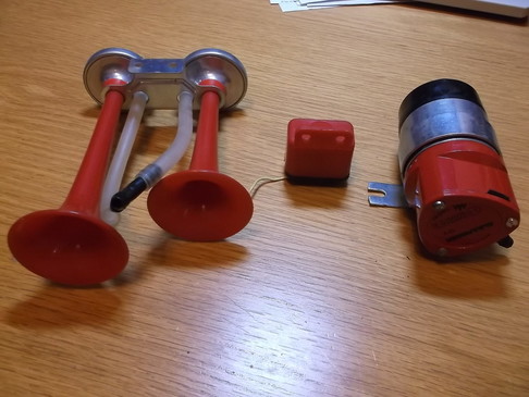
This shows the compressor, horns and operating relay after refurbishment. Even the relay was made in Italy. Changed days indeed!
As i seem to have used some of the plastic tubing for some other job in the past i will have to get some replacement lengths. As a result i had to test each horn separately attached to the compressor. The compressor and horns worked as expected, frightening all the birds, neigbours and myself in the process!
