Background : D.I.Y Propagator (Mains)
I always wanted to use propagators to germinate seedlings as early as possible in the season and put them in the greenhouse, however the problem is that all of the commercial ones that have a variable temperature control are very expensive, around £50-£60. Fixed power/temperature models of a similar size to this one are available for £15-£20 but these can have difficulty maintaining a constant heat under the seedlings when the ambient temperature is low such as in a greenhouse in winter. I decide to try to make my own more permanent propagator from as many components i already had after having great success with a temporary propagator set up used over the past couple of years using the same components on a bench set up. I looked around for a suitable housing for the electrical components but never found anything suitable or if it was too expensive.
After a bit of lateral thinking i came up with the idea of constructing all of the propagator casing from seed trays and some 6mm waterproofed plywood as a base. I had purchased an electronic temperature controller unit a couple of years earlier and had used this in various temporary projects. The mains transformer is a 12V-0-12V, 2Amp unit purchased 30 years ago from Tandy/Radio Shack for experimenting.
After a bit of lateral thinking i came up with the idea of constructing all of the propagator casing from seed trays and some 6mm waterproofed plywood as a base. I had purchased an electronic temperature controller unit a couple of years earlier and had used this in various temporary projects. The mains transformer is a 12V-0-12V, 2Amp unit purchased 30 years ago from Tandy/Radio Shack for experimenting.
The base was made from two pieces of scrap 3mm general purpose plywood glued together, trimmed and then treated with PVA adhesive/sealant to water proof it for use in the greenhouse.
Four rubber feet from an old PC case were recycled to make feet for the plywood base. They were secured in place using stainless steel nuts bolts and washers.
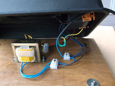
The casing to house the electronics of the propagator are housed under an upturned seed tray. An opening was cut into the upturned seed tray to allow the temperature controller to be mounted. The orange sliding securing tabs can be seen in the photograph holding the controller in place.
The transformer was bolted to the base along with some terminal block which allowed the components to be wired together. The mains cable, recycled from a PC power lead was fed through a hole drilled in the seed tray and protected with a rubber grommet.
Two seeds trays were used to construct the casing of the propagator.
The two seed trays were secured together using six of the drainage holes already present which were drilled out to 5.5mm so that 5mm stainless steel hex button bolts and nuts could be inserted. The remaining drainage holes in the seed trays were sealed using small drops of hot weld glue which was allowed to harden and then trimmed with a sharp craft knife.
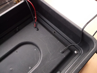
Holes were drilled and grommets installed in both seed trays to allow the power cables to the resistors and the temperature sensor to be passed through to the upper seed tray.
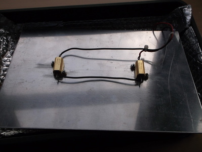
The heating element of the propagator is provided by two aluminium clad wire wound power resistors bolted to a 3mm thick piece of 200mm x 300mm aluminium sheeting.
Two resistors were used , wired in series to ensure that the heat is disipated evenly over the entire surface of the plate. One resistor at the centre of the plate may lead to a 'hot spot' at that point.
The components were selected to produce a heat output of approximately 12Watts per square foot of propagator.
This photograph shows the underside of the heating plate with the resistors bolted in place.
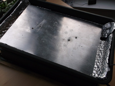
This photograph shows the inside of the propagator tray. The inside of the tray has been lined with a double layer of metalised bubble insulation to reflect all of the heat in the propagator upwards towards the seedlings. It also helps prevent heat escaping through the plastic reducing efficiency and increasing running costs.
The heating plate has been installed and the resistor securing bolts can be seen at each end.
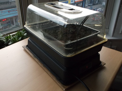
This picture shows the completed unit being bench tested. A seed tray has been placed on the heating plate and the temperature probe has been placed in the soil.
During testing a second thermometer with a remote probe was used to verify that the set soil temperature was being maintained in the propagator.
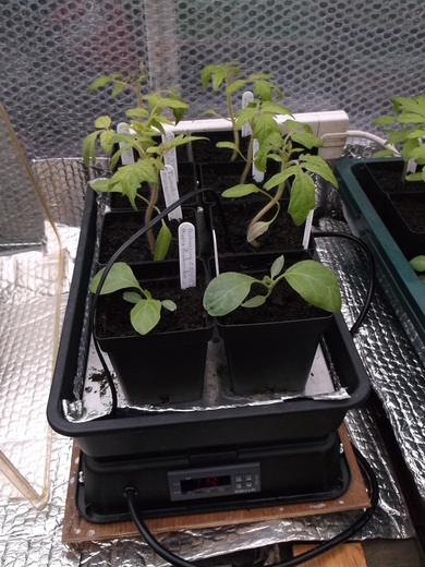
This picture shows the propagator in use in the greenhouse in March 2015.
The cover has been removed to allow a clear picture to be taken.
The temperature probe can be seen inserted into the compost of one of the tomato seedlings.
The propagator has performed extremely well germinating tomatoes, aubergines, begonia and impatiens seedlings and has easily matched the success rate of the commercial propagator i have and repaired a few years ago.
