Background
Recently my Mum's electric blanket stopped working. Fortunately it is the type with plug in controllers and as it was a double blanket i was able to swap the other controller into the side my Mum uses while i looked for a replacement or tried to repair the current one.
From the dated codes on the components i could tell that the controller was manufactured in 2009 so it is not that old. As a replacement controller costs between £25-£35 i thought it was worth while trying to repair the unit and at the same time find out a bit more about how it works before purchasing a replacement one.
The first job was to check the fuse in the mains plug. This was intact so the next step was to open the case of the controller.
After a few minutes of teasing around the case i managed to get the two halves apart. Unfortunately separating the two halves self destructs the clips within the case as the plastic tabs are designed to break off. This is presumably a safety feature to discourage amateur repairs which could result in serious injury or death if not done properly. Assuming i manage to repair the unit i will need to find a safe way of closing and securing the two halves of the case.
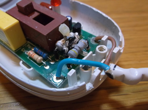
When i opened the case it was obvious where the problem was as can be seen in this picture. The black and white 'blob' in the foreground consist of two resistors with a thermal fuse sandwiched between. The three components were covered with thermal transfer compound( the white material) and the three components were held in good thermal contact by a cable tie(zip tie) wrapped around the components. When i opened the case i was not sure if the cable tie was intact.It looked to be very thin at one point either caused by excessive tension when installed or by the excessive heat due to being in contact with the resistors. I removed the white heat transfer compound which had long since stopped doing its job. It had turned into a stiff sticky white mass. When i removed this i could see that the body of one of the resistors was badly damaged and showed signs of heat damage. I traced the circuit board tracks and found that the two resistors were of the same value connected in parallel. I suspect that at some point the resistors got too hot and the fuse failed or that one of the resistors failed causing the SCR in the back ground to fail which then blew the fuse due to excess current rather than temperature. The SCR in the back ground(MCR100G-8) has some strange dark stains on the PCB beneath it indicating that it may also have failed. As can be seen in the picture the mains cable sleeving had been in contact with the resistors and the heat had been high enough to cause scorching as shown by the large black mark at the very end of the sleeve.
When i opened the case it was obvious where the problem was as can be seen in this picture. The black and white 'blob' in the foreground consist of two resistors with a thermal fuse sandwiched between. The three components were covered with thermal transfer compound( the white material) and the three components were held in good thermal contact by a cable tie(zip tie) wrapped around the components. When i opened the case i was not sure if the cable tie was intact.It looked to be very thin at one point either caused by excessive tension when installed or by the excessive heat due to being in contact with the resistors. I removed the white heat transfer compound which had long since stopped doing its job. It had turned into a stiff sticky white mass. When i removed this i could see that the body of one of the resistors was badly damaged and showed signs of heat damage. I traced the circuit board tracks and found that the two resistors were of the same value connected in parallel. I suspect that at some point the resistors got too hot and the fuse failed or that one of the resistors failed causing the SCR in the back ground to fail which then blew the fuse due to excess current rather than temperature. The SCR in the back ground(MCR100G-8) has some strange dark stains on the PCB beneath it indicating that it may also have failed. As can be seen in the picture the mains cable sleeving had been in contact with the resistors and the heat had been high enough to cause scorching as shown by the large black mark at the very end of the sleeve.
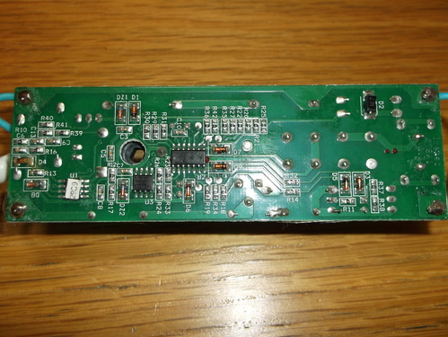
The underside of the PCB did not show any signs of damage. The two IC's in the middle area of the board are LM339 and LM358. The IC to the left with a white label has a Microchip logo on it so i assume it is some type of micro-controller which is used to implement the timer function.
The components required for repair are:
- 1 x MCR100G-8 Thyristor(SCR)
- 2 x 440 Ohm 2W resistors
- 1 x115 Degree Centigrade thermal fuse.
- 1 x 115 Degree centigrade or higher cable tie.
