Background
I have a small number of HP laptop power supply units. A few months ago one of them started to make a crackling/arcing noise. Initially i thought it was coming from the area around the output where the DC cable exited the case as the cable insulation was damaged. I checked all the connections but the power supply stopped working. I set it aside to look at it at a later date. If it was repairable i would do so as these are well made reliable units and the failure rate while working with large numbers of these was very, very low. If it was not repairable i planned to salvage what ever components i could.
When i opened up the case i found that a solder joint had failed on the mains input connector and a second one looked to be heading the same way.
When i opened up the case i found that a solder joint had failed on the mains input connector and a second one looked to be heading the same way.
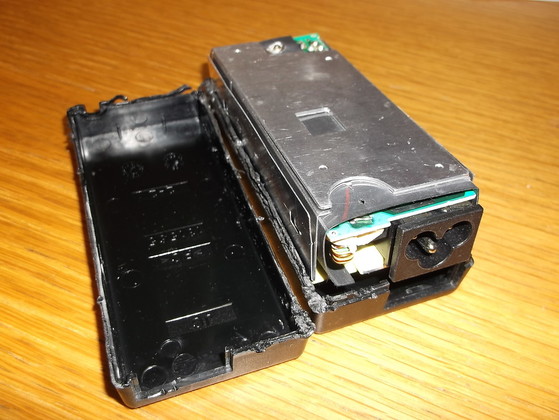
The case was not at all easy to open. There were no screws and or visible clips and in the end it had to be carefully cut open and as a result was destroyed.
The two halves of the case appeared to have been very carefully glued or ultrasonically welded together.
Fortunately great care was taken to open the case as the metal RFI/EMI shields were immediately inside the case with no clearance. between them. The metal shields also serve as a heatsink distributing the wasted energy evenly around the case as there are no ventilation holes.
The Printed circuit board was held in place within the case with some sort of sealer/adhesive which was used to cover many of the components.
Once the PCB had been removed from the case it was connected to the mains and tested. As soon as the AC power was applied small sparks were seen shooting out from under the mains connector.
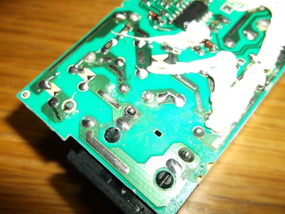
The underside of the PCB was examined and the source of the problem was found.
One of the solder tabs of the mains connector was damaged and was no longer making good contact with the solder pad. Any slight movement caused the arcing seen when connecting the mains cable.
The other mains connector solder tab was also showing signs of failure. The body of the tab can clearly be seen within the solder in the lower right hand corner of the picture.
I suspect that the mains connector solder connections have failed over the approximately 10 years of use due to the continual insertion and removal of the mains lead. The mechanical forces involved have caused the connector tabs and solder to come apart resulting in a poor quality connection hence the arcing which on one of the connections caused the solder to be eaten away.
The connections were de-soldered, cleaned up and then new solder applied.
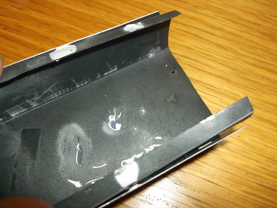
This picture shows the insulating liner of the power supply which protects the PCB components from the metal RFI/EMI shields.
The white marks are where the sealant/adhesive was used to hold all the shielding and the plastic casing in place.
The mark to the right hand end of the insulator below the small hole is where the mains connector was arcing. The small amount of debris from the arcing was cleaned off and the liner itself and the metal shields cleaned of the remains of the sealer\adhesive.
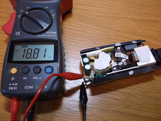
The power supply was then tested with a multi-meter connected to the DC output.
There was no load connected so the output voltage was a little higher than the 18.5V the device is rated at.
The mains connector was inserted and removed several times and there was no arcing from under the connector.
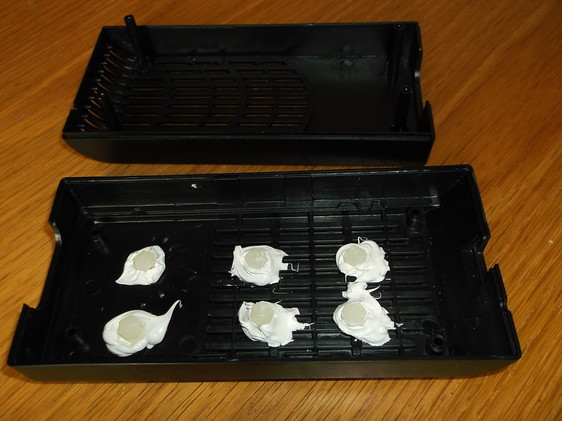
As the PSU is working a new case was purchased to house the module. The casing chosen was much larger than the original case to allow for the mains connector to be mounted in the centre of the opening as it was offset in the original one.
The PSU module has no mounting points and as it is a very compact design there was no space to drill the PCB to create some.
It was decided to therefore use a technique used in so many mobile phones, MP3 players and other very compact portable devices including this PSU, i.e use adhesive. It is not a pretty solution but it does work so this is something of an experiment as far as equipment repairs go!
Some nylon standoff's were modified to remove the threaded end and the securing clip end. The standoff's ensured the PSU would be at the correct height to allow the mains cable to be inserted. The outline of the PSU was marked on the base of the new case. The adhesive was applied to the case and then the standoff's were stuck into the adhesive.
The adhesive was left in a warm room for two days to allow it to fully cure..
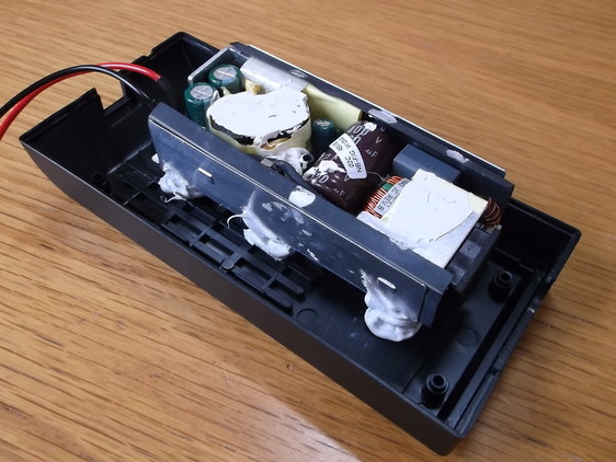
New flying leads were added to the output of the PSU to replace the ones that had failed. These will be connected to the original lead when the PSU is fully re-assembled.
Adhesive was applied to the tops of the standoffs. The metal casing of the underside of the PSU was lightly sanded and cleaned to create a good surface to apply the adhesive to.
The PSU was then carefully aligned and placed onto the adhesive and standoff's.
The PSU was left for 24 hours to allow the adhesive to cure.
After the adhesive holding the module in place had set, the cover was re-installed and two cable ties were used to hold it in place.
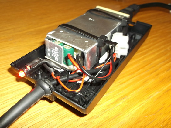
The hole for the LED already present in the case had to be enlarged. A plastic clip/holder was glued to the lower half of the case.
A series current limiting resistor was soldered to the LED and wires were soldered and then connected to the PSU output wires.
The output lead was connected to the LED and the PSU output wires via a section of 2-way terminal block.
The wires were carefully routed inside the case to avoid being crushed and to keep them away from any hot components.
The PSU was tested with the case open then retested with the case in place.
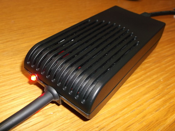
This picture shows the PSU case completed and under test.
The recycled PSU was left under test connected to a dummy load for 3 hours. The case got quite warm to the touch however the slots seemed to be doing their job and keeping the PSU at a safe operating temperature.
Another piece of perfectly usable equipment saved from landfill or the electrical scrap yard!
