Background
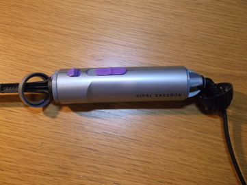
My Mum has a electric heated hairbrush which she uses regularly. However recently the on/off switch had become a bit unreliable and it would not switch on or stay on when it did go on. It was not a particularly expensive item and she did consider buying a replacement but i thought it was worth a couple of hours to investigate if it could be repaired and if not i would gain a little more experience of how it works.
The unit had no visible screws or other fastenings so either it was glued together or clipped together. I used a stiff blade of a penknife to tease and probe apart the casing to see what i could. I found that the entire unit was held together by the two end casings which simply squeeze over the ends of the device and hold the two half shells together.
In this picture the two end pieces have been removed which allow the two shells to be separated to get access to the internal components.
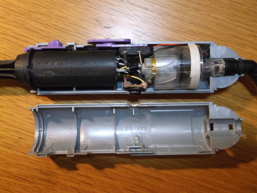
With one half of the two shells removed the internal components can be seen.
The heating element is enclosed in the black housing on the left. This is made of some type of glass filled plastic making it heat resistant. The on/off, heat setting and motor speed switch can be seen at the top of the unit.
The motor and mains input lead which uses an interesting rotating contact system are at the right hand end of the unit.
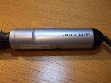
The black control on the bottom of the unit is the mains voltage selector, (110/220V) switch.
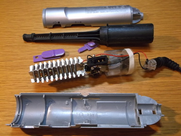
This picture shows the unit dismantled into its sub-assemblies. The central unit shows the heating element with its protective cover removed.
The motor speed and heating are controlled via a simple switch and diode assembly. On the low speed/low power setting the mains voltage is fed through a single rectifier diode so that the motor and heater are supplied only every positive half cycle of the mains. On the high speed/high power setting the mains voltage is fed through a full wave bridge rectifier so that the motor and heater are fed every half cycle of the mains. It is a simple but effective way to implement the speed and heater control.
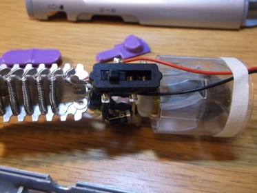
This picture shows a close up of the switch. The switch is an open frame construction type and the contacts can be seen in the bottom of the switch. The slider section slides over the contacts connecting the input and output wires controlling the voltage supplied to the heater and motor.
Before taking the picture this was filled with dust, fluff and hair some of which was stuck under the sliding section of the switch. This stopped the contacts and the slider making contact which would explain why the unit failed to operate reliably.
The dust,fluff and hair was removed from the switch and from the rest of the unit. Some new electrical contact grease was applied to the switch as the grease already present had mostly dried out.
The unit was then carefully re-assembled and tested before being returned.
The entire job took less than 90 minutes including trying to find the tube of electrical contact lubricant, less than the round trip time to the recycling yard!
Repairing this unit does leave me wondering how many other units have been discarded because of a similar problem when in fact there was nothing wrong with them other than requiring a clean.
