Background
I plan to fit a rear view camera system to my Mother's Mini-Crosser mobility scooter as the rear view mirror is difficult to use due to the vibration while moving and the restricted view due to the mirror position and the rear quarter pillars at the rear. I was able to find a system that worked off 24V however on closer inspection and talking with the supplier i discovered that the LCD would work from 10V-30V but the camera would only work from 12V. It would be possible to tap into the 12V and 24V points of the battery but i was not too enthusiastic about this. I decided to produce an on board voltage regulator that would provide 24V for the LCD and 12V stepped down from the 24V for the camera.
Initial thoughts were to use a simple 12V TO220 packaged regulator such as a 7812 or an LM317 plus a couple of resistors to produce 12V. This seemed quite straightforward until it came to the thermal calculations. The camera and LCD are quoted as consuming approximately 3W which implies that as the voltage is being halved, the 12V regulator would have to dissipate 3W and would therefore require a heat sink. After some calculations and prototyping which confirmed my reservations about managing the heat i decided to change track and build on the development of the PIC12F675 DC-DC converters previously used to drive 12V LED lamps from low voltage power sources such as battery packs.
Initial thoughts were to use a simple 12V TO220 packaged regulator such as a 7812 or an LM317 plus a couple of resistors to produce 12V. This seemed quite straightforward until it came to the thermal calculations. The camera and LCD are quoted as consuming approximately 3W which implies that as the voltage is being halved, the 12V regulator would have to dissipate 3W and would therefore require a heat sink. After some calculations and prototyping which confirmed my reservations about managing the heat i decided to change track and build on the development of the PIC12F675 DC-DC converters previously used to drive 12V LED lamps from low voltage power sources such as battery packs.
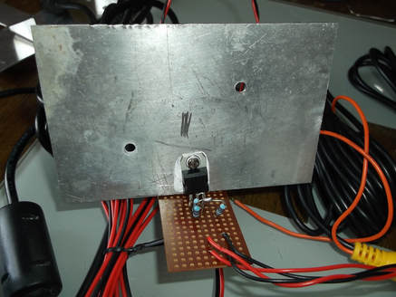
My initial thoughts were to use a simple 12V three terminal regulator or LM317T in a TO220 package. In this picture an LM317T is used with a couple of resistors to set the output at 12V using 24V as the input.
The LM317T needs to dissipate 3W at least and as a result requires a substantial heat sink. Mounting locations in the final application, a mobility scooter were limited and as most of the body is fibre glass the heat has to be carefully managed to avoid damage.
The heat sink shown was calculated to allow a surface temperature of approximately 40 degrees centigrade. An alternative heat sink was designed with two vanes and half the height which would keep the surface temperature to 30 degrees centigrade and would be easier to package.
Ultimately the packaging was going to be too difficult so i decided to go down an alternative route using a switch mode DC-DC converter.
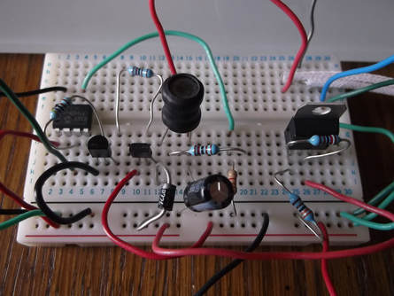
A step down ("Buck") converter circuit was designed using a PIC 12F675 micro-controller to drive the converter circuit, measure the feedback voltage and implement the control algorithm.
An LM317T in a TO220 package was used to convert the 24V input to a 5V output to supply the PIC. As the current drawn by the PIC is very low it should be possible to replace the TO220 package with a TO92 package as there is very little power dissipation.
The circuit was designed with a nominal output of 12V at 300mA.
The control program for the PIC 12F675 was designed and developed on the Microchip MPLABX IDE using the Microchip XC8 'C' compiler. The control program implements assembler code for the time critical elements mixed with 'C' code.
The prototype circuit was assembled on breadboard and the operation verified with a series of 'dummy' loads, such as LED lamps.
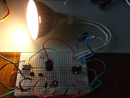
As the designed output load is 12V at 3W, a 3W LED lamp was used to test the circuit.
The output driver stage consists of a single ZTX551 PNP bipolar transistor. It is small, has a high gain and can carry a continual collector current of 1A. While driving the LED lamp for over 30 minutes the transistor was only luke warm. This was very encouraging as no heat sinking should be needed for this circuit.
The prototype circuit was assembled on breadboard and the operation verified with a series of 'dummy' loads, such as LED lamps.
As the designed output load is 12V at 3W, a 3W LED lamp was used to test the circuit.
The output driver stage consists of a single ZTX551 PNP bipolar transistor. It is small, has a high gain and can carry a continual collector current of 1A. While driving the LED lamp for over 30 minutes the transistor was only luke warm. This was very encouraging as no heat sinking should be needed for this circuit.
More information to follow soon.....
