Background
In December 2015 my mother purchased a Mini Crosser Cabin scooter. It was supplied with two Numax 24V ,7Amp chargers. One was in very good condition. The other had obviously been outside, had signs of corrosion on the end plates and screws and when the case was opened it was covered with cob webs and dead insects and moths.
The charger was tested to ensure that it would charge the batteries as there was no point in refurbishing it until it was repaired and working.
The charger was tested to ensure that it would charge the batteries as there was no point in refurbishing it until it was repaired and working.
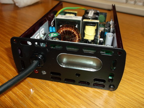
 Battery Charger with top cover removed.
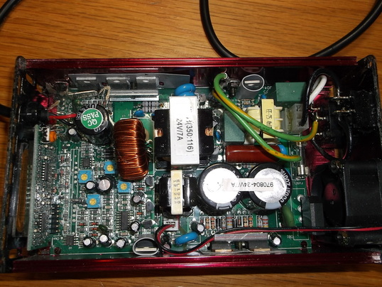
The top cover was removed to inspect the inside of the charger.
All the main components looked to be in good condition. There was no sign of bulging of the sides or tops of the electrolytic capacitors.
The heat sink compound of the semiconductors looked a little dry so needed to be inspected and renewed if required.
All the internal wiring was in good condition.
The charger is based on the Texas Instruments TL494 switch mode power supply IC.
A micro-controller and LCD display mounted on a daughter board controls the charging process and displays the charging status.
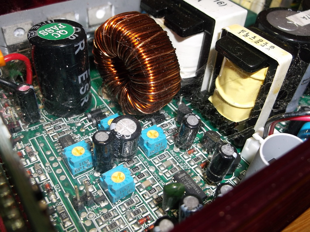
Charger components covered with cob webs and dead insects.
The internal components were covered in a film of cob webs with insects, spiders and moths caught up in it. It is important that this is removed as moisture/condensation can gather on the webs causing current leakage paths at least and at worst short circuits .
|
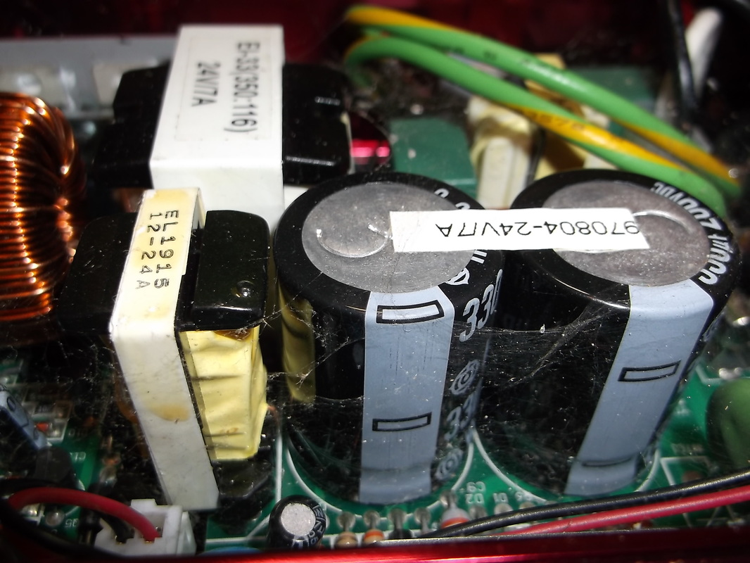
Capacitors show no signs of damage but also covered in cob webs.
The main inductors and capacitors look to be in good condition with no signs of bulging on the capacitors or moisture damage to the inductors.
|
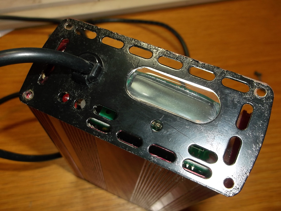
The end plate shows signs of water damage and corrosion.
The front panel with the LCD and charge status LED's is corroded around the edges where moisture has caused the paint to blister and flake.
|
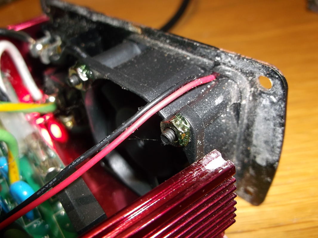
End plate and inside of case show signs of water and corrosion.
The corrosion extends to the inside of the charger. This picture shows the rear of the cooling fan.
|
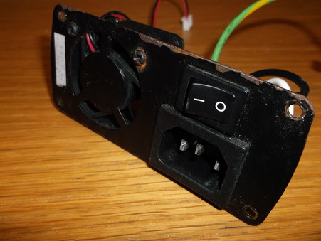 End plate removed shows serious paint flaking and corrosion.
One of the end panels was badly corroded. It was disconnected from the main printed circuit board and a couple of connectors were de-soldered. This allowed the on/off switch, mains input connector and fan to be removed from the panel.
The flaking paint was removed and the rust and paint rubbed down using fine sand paper.
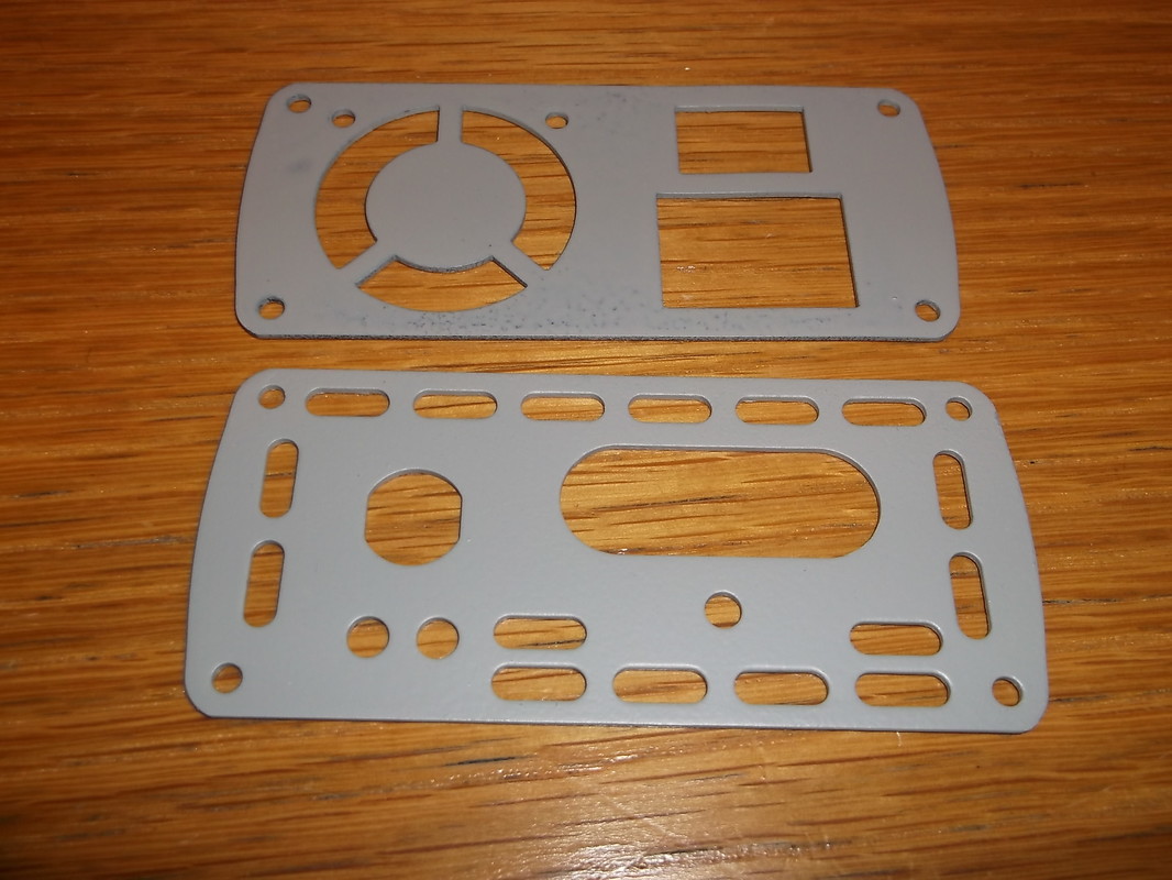
End panels cleaned and primed.
After both end panels were sanded they were carefully cleaned to ensure all debris had been removed. They were then carefully sprayed with several thin coats of grey primer in preparation for several thin coats of satin black top coat.
The primer was allowed to dry for 24 hours between each coat. 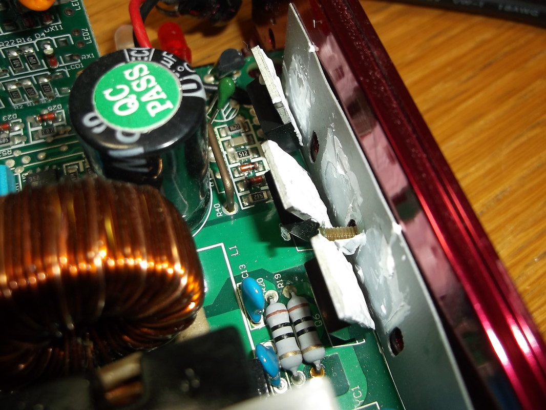
Semiconductors bent forward and new heat sink compound applied.
All of the semiconductors looked as if they needed heat sink compound applied. The securing clips and bars were removed and the semiconductors carefully bent forward. The remains of the old compound were cleaned off and a fresh coating applied.
|
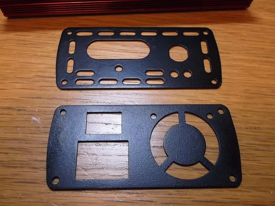
End panels sprayed with black satin paint.
After the grey primer had been allowed to dry for several days in a warm room several thin coats of black satin paint were sprayed on. Each layer was allowed to dry for 24 hours. Before the last coat was applied the previous coat was lightly sanded with very fine glass paper to provide a good bonding surface for the final coat. The panels were left for seven days in a warm room to allow the paint to fully harden.
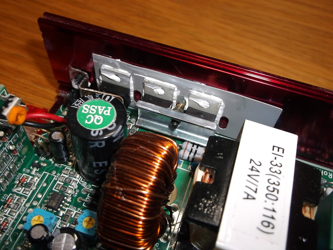
New heat sink compound applied and semiconductors clamped in place.
With the new coating of heat sink compound applied the semiconductors were carefully bent back into place and the securing clips and bars were securely screwed back into position.
|
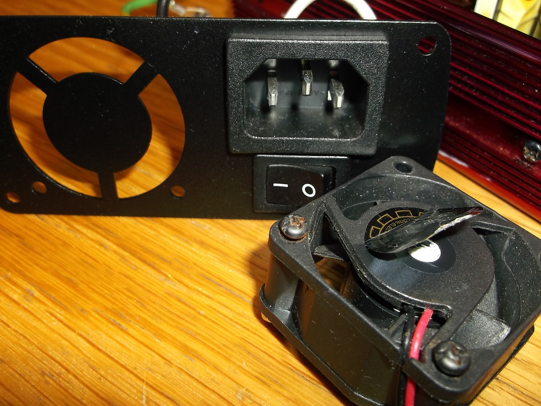
End panel partially assembled and fan bearing lubricated.
While the end panel was disassembled the opportunity was taken to peel back the label covering the fan bearing and apply some lubrication. The label was then put back in place.
|
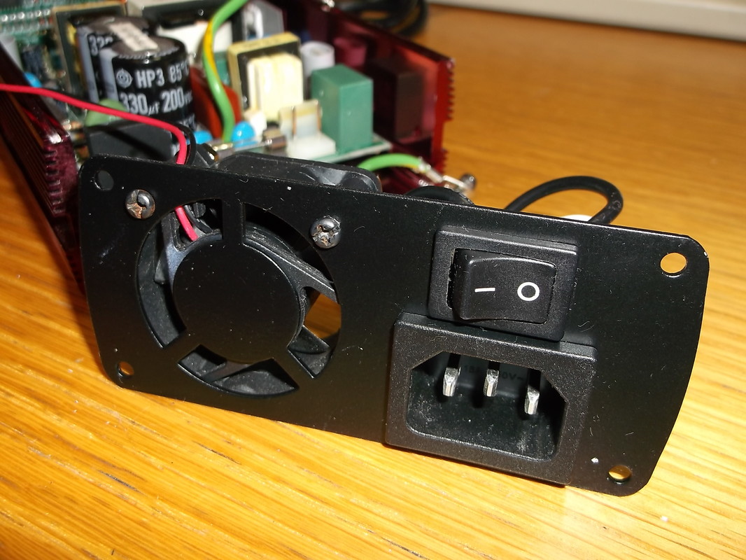
End panel fully re-assembled ready to be installed.
When all of the components were re-installed on the end panel the connections on the rear were re-soldered and the mains connector contacts re-assembled. The end panel was then re-installed onto the casing.
|
 Front panel installed on case.
The front panel was a little simpler than the end panel to re-assemble.
The plastic screen was clipped back into place and the cable strain relief grommet squeezed back into the mounting hole.
The front panel was then mounted onto the case.
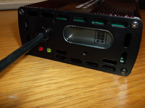
After the front and end panels were mounted on the case, the top panel was screwed back into place and the unit was tested.
The output voltage was measured in the "Float" mode at 27.4V which is what was expected.
There is now a replacement charger available for my Mum in the event there is a problem with the current one.
Before and After......

Front panel before refurbishment.
|
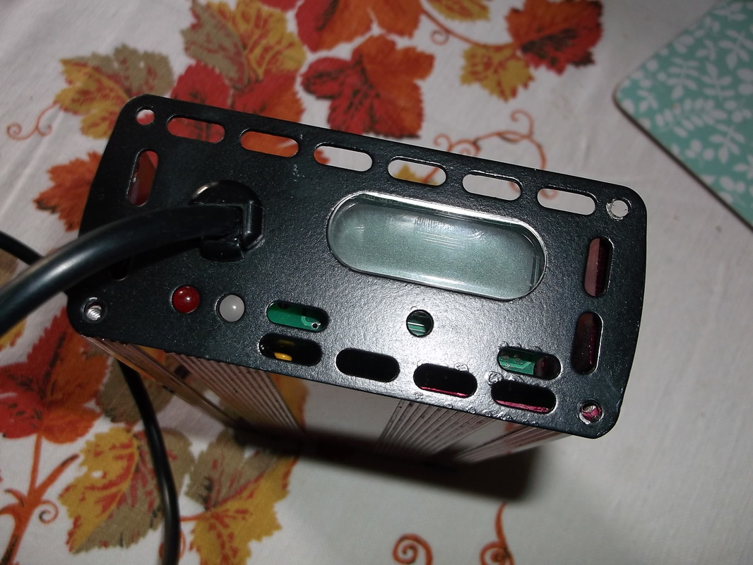
Front panel after refurbishment.
|
