Background
I have developed a number of drive circuits to drive LED lamps over the past few years. These have all been on the basis of what is often described as "chopper" control of the LED current. These "chopper" control circuits were developed using discrete IC's such as the LM339, LM393 and LM319. If i wanted to pulse the light for any reason then an external device such as a PIC would be required.
After developing the PIC 12F675 based DC-DC step up voltage converter i decided to try to use the internal features of this device to implement chopper control of the LED current.
I implemented this using the internal comparator of the 12F675, configuring it to drive an external transistor which in turn drives the LED lamp. In the initial implementation the 12F675 runs some code which configures the internal comparator and then has no further involvement in the control of the device. The CPU was simply left in a code loop. In effect a microprocessor had been configured into a comparator! Rather a waste of all those hundreds of thousands of transistors!, however, in the upgrade the CPU will be used to pulse the LED lamp with different patterns selectable from an external switch.
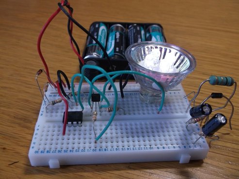
I based the development circuit on the piece of breadboard used to develop the PIC DC-DC converter circuit. In this picture the components to the right were the ones removed from the DC-DC converter to create the current "chopper" version together with a few connection changes. The PIC DC-DC converter used a low number of components and this circuit reduces that number further.
The circuit is shown here running from 4x1.2V Ni-MH batteries driving a 12V, 0.4W LED lamp.
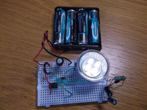
This picture shows the circuit working from the battery pack.
Because of the circuit configuration it is not possible to program the PIC in circuit so it has to be removed and plugged into a programmer. The in-circuit programmer is unable to detect the PIC when used in this circuit.
The light output is very good from this configuration considering how simple the circuit is and how few components are required.
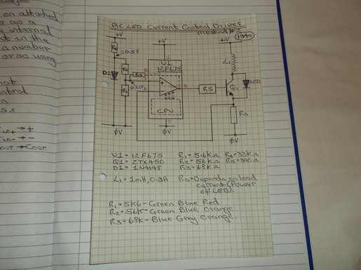
The peak current through the LED lamp is set by a diode and resistor network generating a reference voltage which is connected to the non-inverting terminal of the internal comparator. The diode is used to create a fixed reference voltage which will not change significantly as the battery voltage decreases.
A current sense resistor is used to measure the current through the LED lamp. The voltage across the resistor is connected to the inverting input of the internal comparator.
The output of the comparator is configured to drive an external transistor via a current limiting resistor.
In this initial implementation the CPU plays no part in controlling the current in the LED other than to configure the comparator when the program starts.
More information on this development to follow soon.....
