Bakground
In early 2017 a friend offered me an old Microsoft XBox and power supply that she was disposing of. I refurbished the XBox and got it going but not being a games enthusiast i had no immediate use for it. A while ago i decided to salvage what i could from it and then send it for recycling. I had however decided to keep the 12V power supply and make some use of it as it provides a handy 12 Amps at 12V and 5V at 1 Amp.
Below is the detail of a simple power supply breakout box project i produced using some components i had lying around that themselves had been salvaged from other items and projects.
The Xbos PSU output cable has red, yellow blue and black cables internally that supply power to the XBox console via a proprietary connector. When the connector is cut off the cables can be bundled together to provide the required supply voltages. The XBox PSU provides a +5V ( @1 Amp) standby voltage on the red cable. When the red cable of the XBox is connected to the blue cable this enables +12V at up to 12 Amps on the yellow cables.
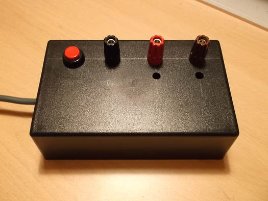
This breakout box provides +5V(@1 Amp) at the red binding post when the PSU is connected to the mains. It will only provide +12V (@12Amps) when the push button is pressed and the yellow indicator LED is lit.
Below is the detail of a simple power supply breakout box project i produced using some components i had lying around that themselves had been salvaged from other items and projects.
The Xbos PSU output cable has red, yellow blue and black cables internally that supply power to the XBox console via a proprietary connector. When the connector is cut off the cables can be bundled together to provide the required supply voltages. The XBox PSU provides a +5V ( @1 Amp) standby voltage on the red cable. When the red cable of the XBox is connected to the blue cable this enables +12V at up to 12 Amps on the yellow cables.
This breakout box provides +5V(@1 Amp) at the red binding post when the PSU is connected to the mains. It will only provide +12V (@12Amps) when the push button is pressed and the yellow indicator LED is lit.
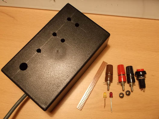
I had a power supply project box which had been lying around since around 1999 and was originally purchased in the Tandy/Radio Shack closing down sale at the time.
I also had some binding posts that were salvaged from old equipment over 20 years ago. They are marked 'RS' and 'Made in UK' so that would give some ideaof their age.
The LED's and strip board were all purchased withing the last few years and surplus from other projects.
I used a large box so as to provide a stable base for the components and while it is in use and also with the view of adding a voltage/ammeter module at a later date.
In this picture the layout has been decided and the holes drilled for the components.
After the holes were drilled the components were securely mounded with the solder tags on the binding posts aligned to make connections as easy as possible.
The box has a +5V and +12V output available at the red and brown binding posts respectively. At a later date i will change the brown post to a yellow using the standard PC PSU colour coding for wires.
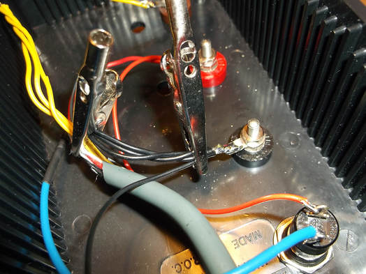
The XBox connector was cut from the end of the cable.
The yellow wires supplying +12V were twisted together and soldered to the brown binding post.
The Black wires providing the GND return were twisted together and soldered to the black binding post.
The red wire supplying +5V was connected to the red binding post and using an extra length of wire to one side of the push button switch.
The blue wire was extended and connected to the other side of the push button switch.
This arrangement means that the breakout box always supplies +5V at the red post but will only supply +12V when the push button is pressed.
The crocodile clips were used to hold cables inplace while additional flying leads were soldered.
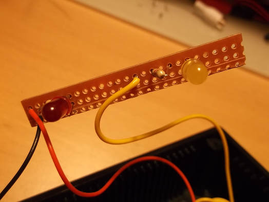
Rather than try to connect resistor, LED's, binding posts and wires together i decided to mount the LED's and resistors on a small piece of strip board and then mount this on the rear of the front panel.
This made connecting the wiring much simpler.
In this picture the LED's and current limiting resistors for the +5V and +12V outputs are shown together with the wires connecting them to their respective supplies.
Small black plastic mounting clips were used to mount the LED's and strip board in place.
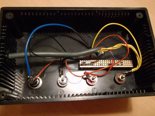
In this picture the internal wiring of the breakout box is completed with the strip board holding the LED's and resistors in place.
The blue wire from the XBox PSU cable was the only one that had to be extended to connect to the push button switch.
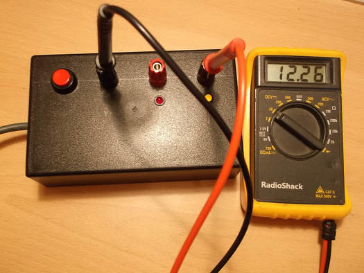
Here the breakout box is being tested.
The red LED is lit indicating that the +5V output is active.
The yellow LED is lit indicating the push button is pressed and the +12V output is active.
The PSU is under little or no load and the DVM shows the current voltage output.
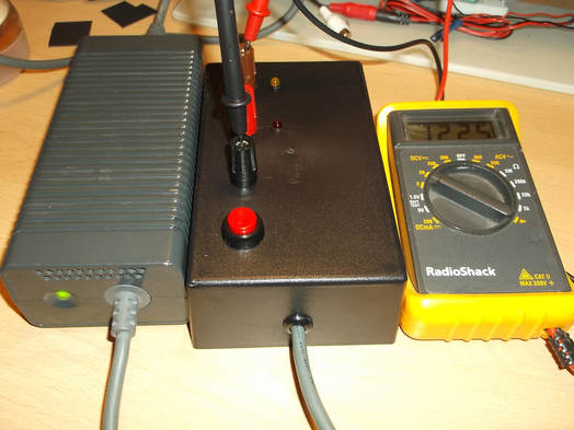
Here the XBox PSU is shown beside the breakout box and a DVM showing the output voltage of the +12V.
When the +12V output of the XBox PSU is enabled the green LED on it is lit. When the +12V output is not enabled the LED is yellow/amber.
I have tested the PSU up to 5A so far and it has worked pwrfectly. This should be a useful power supply for lots of development projects and prototypes given its very useful 12Amps output on the 12V rail.
