Background
Over
the past 3-4 years i have become quite exasperated at the number of
AC-DC mains adapters for electronic equipment that have failed. The most
disappointing thing is that the mains adapters that have failed are not
supplied with cheap unbranded equipment but with well known brand
names. For example, the 12V mains adapters supplied with the following
equipment have failed in this time.
I decided to produce my own 12V supply for routers, modems, external disk drives etc. Rather than build individual units for each piece of equipment i decided to try to recycle a PC PSU from an old PC.
The equipment to be powered from this unit will be:
Currently these pieces of equipment are powered from plug top AC/DC adapters.
I happened to have a low profile desktop PC with a 200 Watt AT style power supply with a built in switch. It had been lying around for about 8 years as i wanted to recycle some of the parts if at all possible and finally a project has come up! I removed the power supply from the PC casing and set it up on the bench to be tested to see if it is still working and is suitable.
- Netgear DG834G Wi-Fi ADSL2+ Router. (Two separate units have failed)
- Netgear S101 Network Attached Storage unit.
- Linksys/Cisco RV082 Router. (Two separate units have failed)
- 3Com 3CR870 Router.
I decided to produce my own 12V supply for routers, modems, external disk drives etc. Rather than build individual units for each piece of equipment i decided to try to recycle a PC PSU from an old PC.
The equipment to be powered from this unit will be:
- Netgear DG834G Wi-Fi Router.
- Linksys/Cisco RV042 Router.
- Netgear 101 NAS disk system.
Currently these pieces of equipment are powered from plug top AC/DC adapters.
I happened to have a low profile desktop PC with a 200 Watt AT style power supply with a built in switch. It had been lying around for about 8 years as i wanted to recycle some of the parts if at all possible and finally a project has come up! I removed the power supply from the PC casing and set it up on the bench to be tested to see if it is still working and is suitable.
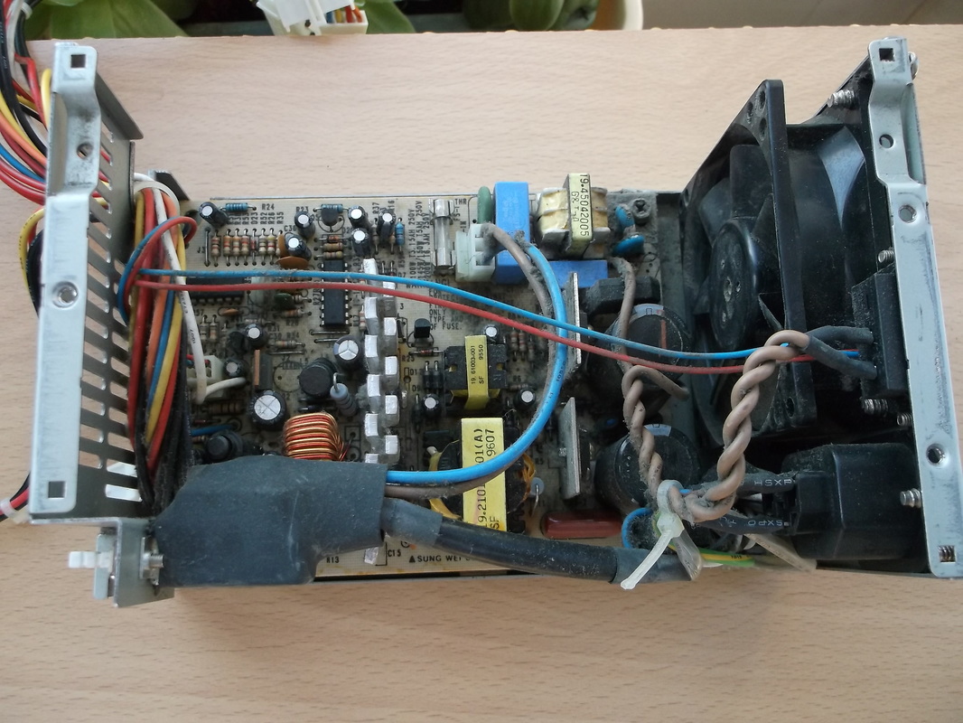
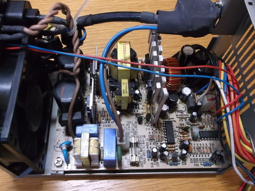
After removing the PSU from the PC the covers were removed to check for any obvious internal damage. The power supply was plugged into the mains to check it would power up. A multimeter was used to check the +5V, +12V, -5V & -12V outputs. All the outputs were within specification. The only problem found was that the fan would not run. I tried using a finger to 'push start' it but this did not help. The power supply was switched off.
All the components were removed from the casing to allow all the dust and dirt trapped between the wiring, switch, fuse and mains connectors to be removed.
While the PCB was removed from the chassis, the dirt and dust was removed from the base and cover. |
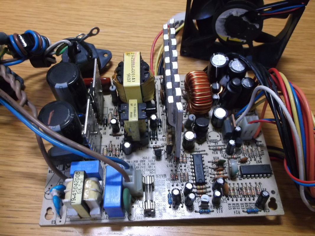
The PSU was as expected filled with dust and fluff. A soft long bristle brush was used to loosen the dust and then a vacuum cleaner was used to remove the dust from around the components.
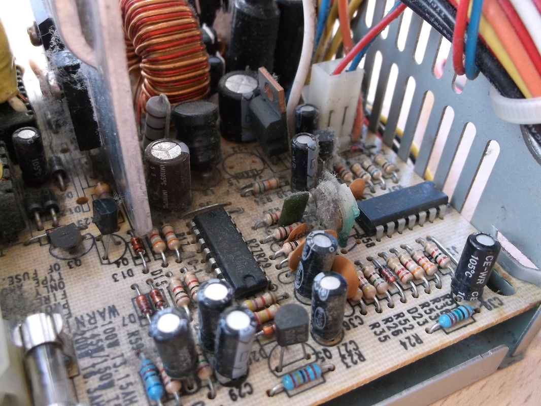
While the covers were off all the components were checked for damage, particularly resistors for heat damage and the electrolytic capacitors for any signs of bulging tops. One resistor showed signs of heat damage but the surface was not cracked. The damage is more due to heat aging rather than abuse. It may need to be changed. 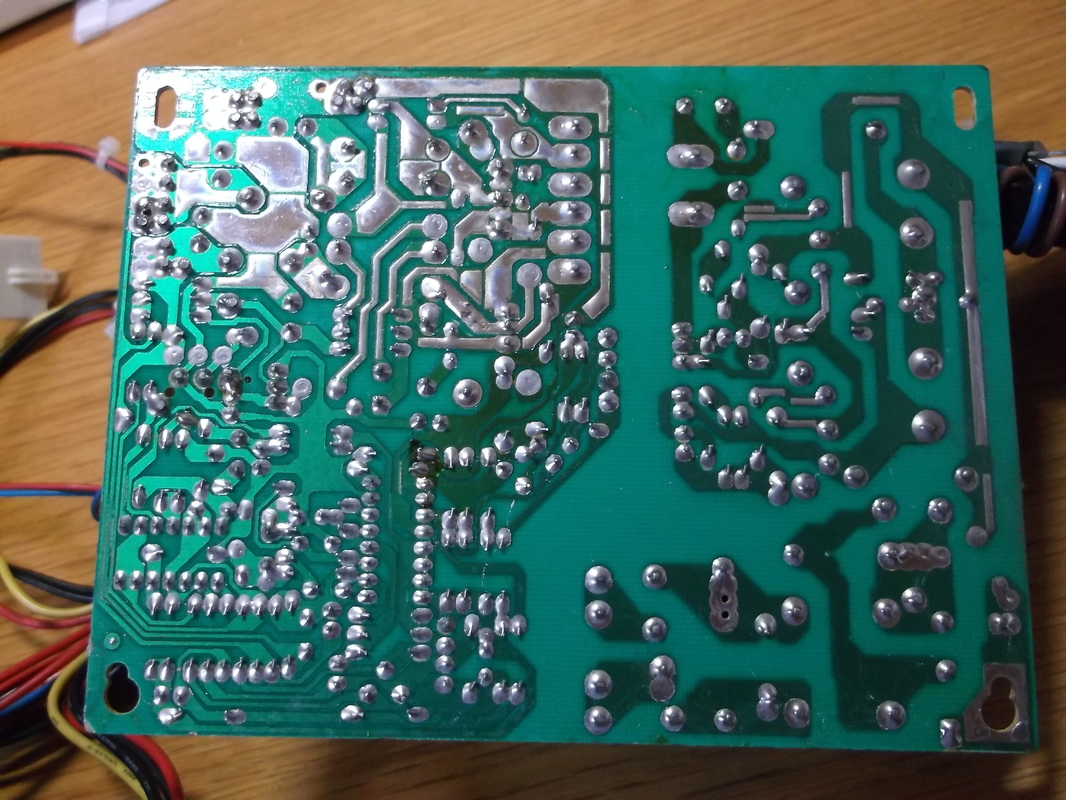
The dust and dirt was removed from the underside of the PCB using a soft bristled brush and vacuum cleaner.
The PCB was inspected for any dry joints or heat damage. No signs of excessive heating or damage were found. |
While the PSU was dismantled, the fan was examined. The rotor was much stiffer than expected indicating that it was probably seized or simply that the bearing had dried out. The rotor did not wobble in the bearing indicating that the bearing was not badly worn or broken. I removed the label and the rubber grommet covering the bearing. There was the remains of dried up grease around the bearing. The bearing cavity was cleaned and a small amount of light oil was applied to loosen up the rotor motion. This worked quite quickly. A small amount of light grease was applied to the bearing and the rotor manually turned to work it in. The rubber bearing cover was replaced and the fan was run from a 6V battery for15 minutes to gradually 'run in' the bearing again. A 6V rather than 12V battery was used so as not to run the fan at full speed until the grease had been worked into the bearing. In the event the fan continues to be troublesome i happen to have an excellent PAPST 12V fan which would be a direct replacement for this one. It was purchased in Leeds in summer of 1995 when i was working there. I used it as a temporary desk fan as it was a particularly hot summer and the office air conditioning was struggling to cope. It was purchased at a surplus equipment and components shop in Leeds, M & B Radio beside the main train station. It was an Aladdin's cave of equipment and components and i spent many lunchtimes browsing and getting ideas for projects. Anyway, back to the PC PSU........
After all the parts were cleaned they were carefully reassembled into the casing.
The PSU was connected to the mains and tested again. This time the fan started as expected and the output voltages were checked. The fan ran quite slowly but this was expected as these types of PSU's have temperature sensitive fan speed controllers that run the fan faster when the temperature of the PSU increases when it is under load.
A couple of aluminium clad power resistors were connected to the +5V and +12V outputs to provide some loading. After 30 seconds the fan speed increased as expected and decreased again when the loads were removed.
The voltage outputs were stable on this AT Type PC PSU with no external loads connected as i suspect it has some internal loads to allow the regulation loop to operate with no external load connected. The casing was re-assembled.
The external circuitry will need to be designed and constructed to allow the +12V output to be distributed to the routers and disk drives and any other equipment requiring a 12V supply.
More to follow soon.......
Update 18th January 2016 : Replacing the cooling fan.
In the past few days the original PSU cooling fan finally failed. The bearing had completely seized. Fortunately i had a spare fan of the correct size available although it is quite a bit thicker than the original. The PSU has been in use powering one Linksys/Cisco router for the past 6 months. Fortunately the load was low so the PSU did not require much cooling and when the fan failed there was only a slight increase in temperature of the case.
In the past few days the original PSU cooling fan finally failed. The bearing had completely seized. Fortunately i had a spare fan of the correct size available although it is quite a bit thicker than the original. The PSU has been in use powering one Linksys/Cisco router for the past 6 months. Fortunately the load was low so the PSU did not require much cooling and when the fan failed there was only a slight increase in temperature of the case.
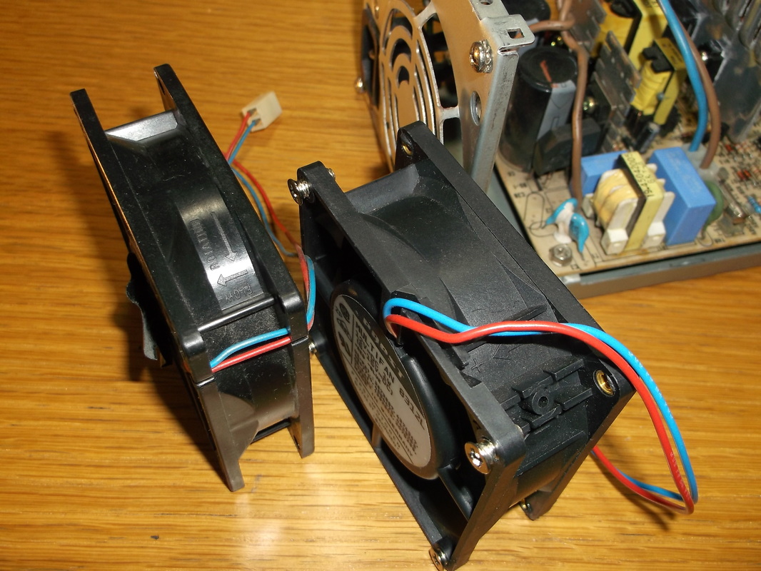
Old failed fan on left, new fan on right.
The PSU was dismantled and the fan was removed. The new fan was test fitted to ensure it would fit in without interfering with any of the other components particularly the PCB. The connector on the new fan was different to the old one so the old connector and part of the cable was spliced onto the new one.
|
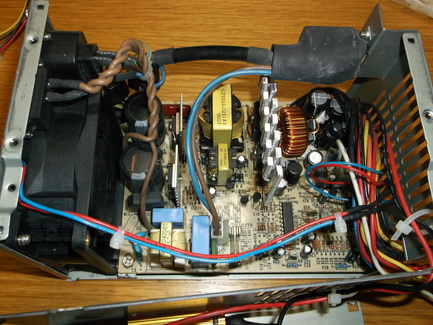
New fan installed and wired to supply.
The new fan was installed and secured in place with the original self tapping screws. The fan was connected into the PSU and the power supply tested to ensure nothing was stopping the fan blades rotating freely.
|
Update 19th January 2016 : Installing minimum load resistors.
I intend to run a number of devices, external disks, routers, modems from this power supply. Some of these will be switched off and on remotely only when they are required such as the disk drives. Some testing has revealed that if the devices were to be switched on or off in the wrong sequence the PSU will switch off as the sudden change in load causes the voltage level to switch outside its operating range and the PSU shuts down to protect the equipment connected to it. The problem was due to the lack of a minimum load on the the 5V supply. Any sudden increase or decrease on the 12V supply caused the PSU to shut down. It is a common requirement that switch mode power supplies have to have a minimum external load to start up and operate correctly unless they have the minimum load built in internally.
Typically in PC PSU's the 5V supply is the one that is in the main control loop. The other supplies, +12V, -5V and -12V are derived from it so this will at least require a minimum load. A load of 1A was chosen for this. As i will be operating primarily 12V devices from this power supply i would prefer this output to be stable so i have set up a 0.5A(approx.) minimum load on this output. In total this means that the power supply is dissipating at least 11W in meeting the minimum load requirements.
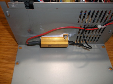 A 5V minimum load resistor installed.
I decided to mount the minimum load resistors inside the case. I had a 5 ohm/50W wire wound aluminium clad resistor which was ideal for the purpose. I cut the 5V and GND wires from one of the Molex disc drive connectors and soldered it directly to the resistor terminals.
The case was marked with the mounting holes and carefully drilled.
The resistor was then mounted on the inside of the case using small nuts, bolts and spring washers.
A generous coating of heat sink thermal transfer compound was applied between the base of the resistor and the case to ensure a good contact.
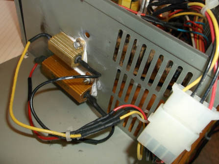 !2V and 5V minimum load resistors and connector installed.
The second power resistor, a 25 ohm/ 25 watt aluminium clad type was installed on the case to provide the minimum load to the +12V line.
A disk drive connector was soldered into the system to allow the top case to be completely removed from the power supply to allow periodic cleaning of the inside.
The power supply was re-assembled and tested. With a router powered from the PSU another 5 ohm/ 50W resistor was connected to the 5V and 12V supplies in turn to test that the power supply would not switch off when the load was either connected or disconnected. The test was repeated several times over 15 minutes. The temperature of the case was monitored during this time to verify that it did not exceed a comfortable 'hand touch' temperature. The voltage of the 5V and 12V outputs were measured to ensure they were within the specification.
The power supply now powers most of the 12 Volt systems i use, routers, external disk drives, cooling fans etc and the individual adapters have been put into storage in case they are ever needed again.
