Background
My mother has a fully enclosed electric scooter which is more like a small electric car than a traditional scooter. It has an optional extra cabin heater but this costs GBP1200 and runs from diesel or paraffin. Being cold in the cabin is not a big problem for her as it heats up from her own body heat quite quickly but this does lead to condensation on the windows which appears very quickly. Opening the sliding windows slightly clears the misting on the windows but does make it a little drafty on windy days.
I decided to install an electric heater to keep the windows clear and provide a bit of heat on particularly cold days. I had seen 12V 100W hand held heaters that could be plugged into a cars accessory socket to quickly defrost windows in bad weather. A bit of research revealed that 24V versions were available for trucks, vans and recreational vehicles. These were typically rated at around 200W. I estimated that 200W in a very confined space would get quite uncomfortable quite quickly and could also drain the battery significantly on very cold days. I decided to make a control circuit that would allow the heater output and therefore the battery drain to be controlled from inside the cabin.
A suitable heater was purchased rated at 24V, 200W. This was used to experiment and develop a prototype heater for the scooter cabin.
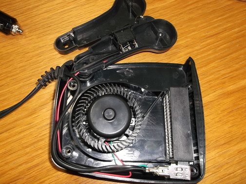
Here the handle and case of the heater unit have been opened up.
The combined on/off and heater control switch are mounted in the handle. The switch allows the fan to operate alone with no heat to circulate air or to operate with the heater element blowing warm air.
The case contains a centrifugal fan and the ceramic heater element. There appears to be no overheat protection or thermal fuse, a problem that will need to be addressed.
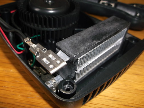
This picture shows the ceramic heating element mounted at the front of the case.
The fan mounted behind it draws air in from the top of the case and blows it over the element at the front.
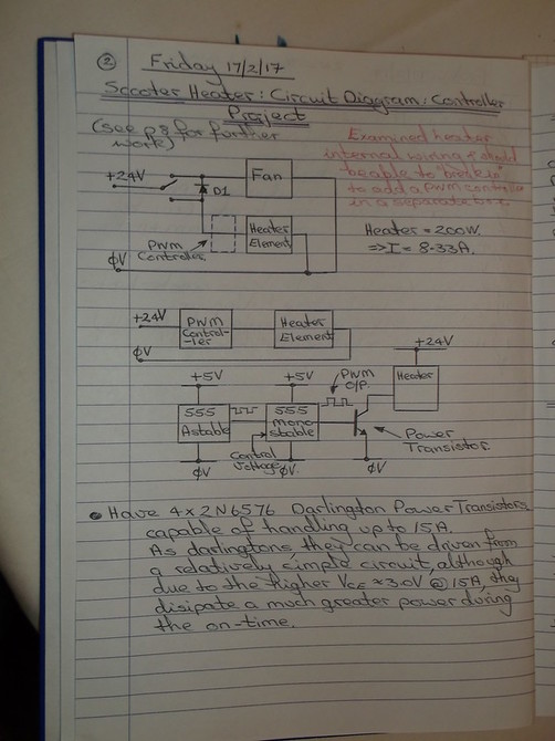
A circuit diagram was created from the internal wiring.
The connections between the switch, fan and ceramic heating element will allow the proposed PWM controller to be inserted into the heater element only leaving the fan to operate from the 24V supply
A block diagram of the control system is shown in this picture
The proposed PWM circuit will use the popular 555 timer IC to control the voltage switched across the heating element thus controlling the power delivered to it.
The controller circuit consists of two 555 timer IC's. The first operates in astable mode generating a stream of short negative going pulses. The negative going output pulses of the astable circuit drive the trigger input of the second 555 timer operating in monostable mode. The monostable output pulse width can be varied creating the pulse width control. The astable circuit sets the frequency of the pulse width
|
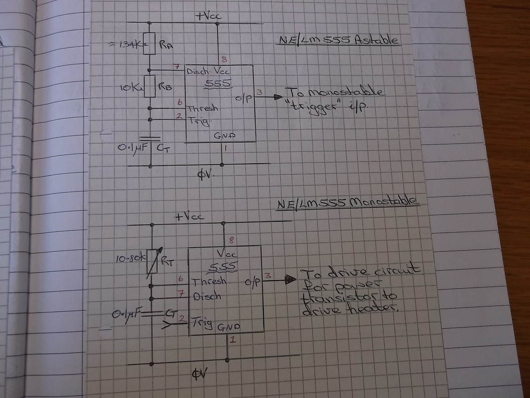
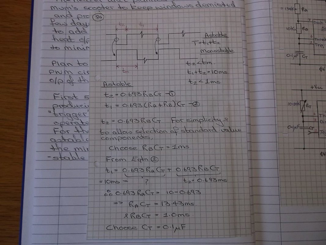
This picture shows the monstable and bistable circuits with the component values calculated.
|
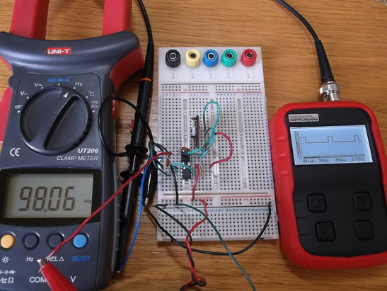
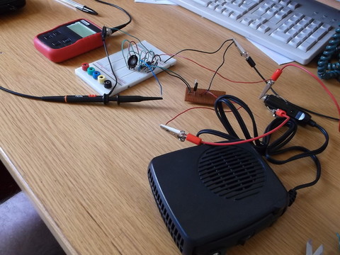
The prototype circuit was constructed on breadboard for testing.
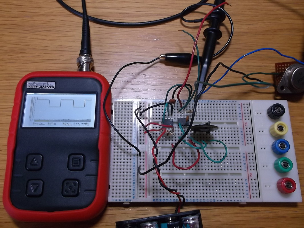
Here the meter on the left shows the measured frequency of 98.06Hz.
The oscilloscope on the right shows the output of the monostable section of the circuit with the pulse width set to the lower level of the range.
The specification of the circuit is:
Pulse frequency= 100Hz
Pulse Width range 1ms to 9ms.
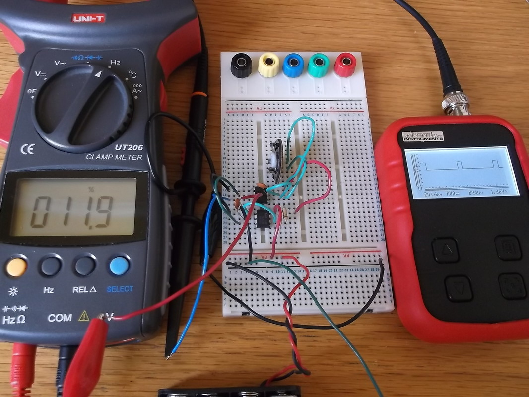
This picture shows the circuit set to the lower range of the pulse width with the meter on the left showing a duty cycle of 11.9%. The oscilloscope shows the output pulse stream.
|
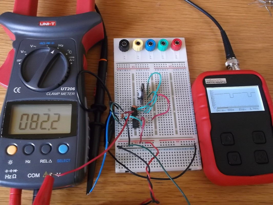
This picture shows the circuit set to the upper range of the pulse width with the meter on the left showing a duty cycle of 82.2%. The oscilloscope shows the output pulse stream.
|
The heater power consumption is 200W. At a supply voltage of 24V this equates to a current consumption of 8.33A.
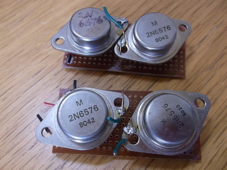
I happen to have a few 2N6576 Darlington Power Transistors left over from a few stepper motor projects i developed many years ago. These are capable of delivering up to 15A.
These can be driven directly from the output of the 555 timer circuit with just the addition of a few resistors.
The transistors have date codes of week 20 and 42 of 1980, so at the time of writing they are over 36 years old. I purchased these in the mid 1980's at Browns Radio in Edinburgh, sadly now long gone. This shop supplied electronic components and parts both new, second hand and surplus.
The design calculations were completed for a simple test circuit running the fan and heater from a 12V supply rather than the rated 24V. The heater current was measured as 6.5A-7.0A. Because the heater element is a PTC ceramic type this was higher than normally would be expected as the fan was running much slower than normal as it was run from 12V rather than 24 and hence the cooling effect was much lower.
In the final system, the fan will be run from 24V and the heater will be run from 24V via the PWM control circuit.
In the final system, the fan will be run from 24V and the heater will be run from 24V via the PWM control circuit.
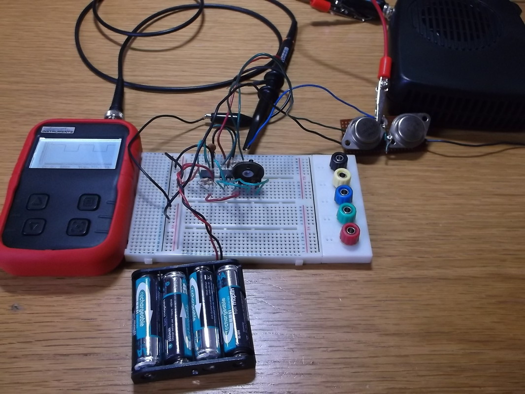
The drive circuit was set up connected to the 12V output of a PC PSU.
The pulse generation circuitry was powered from a battery pack. The high current circuitry of the drive output was connected together with flying leads and crocodile clips. This allowed for easy disconnect in the event of any problems and the circuit was very temporary anyway as calculations show that a darlington transistor would dissipate too much energy and would require a lot of cooling. Only one of the transistors shown in this photograph was connected to drive the heater and fan. |
This picture shows the oscilloscope displaying the collector voltage of the darlington drive transistor at roughly 50% duty cycle. Even at this drive level and using a 12V supply the darlington case temperature rise was very high. As the design calculations had shown the darlington would require significant heat sinking.
The circuit worked as expected and the heat output from the heater element was good, even when run from 12V. |
It was always clear that the darlington power transistors would dissipate too much heat to be usable in the final design however they did allow testing of the PWM circuit and the heater/fan.
The darlington transistors were replaced by IRF540 N Channel power MOSFET devices which were ordered online.
In order to drive the MOSFET correctly it requires at least 10V applied between the gate and source connections. This was achieved by simply powering the PWM circuitry from the 12V supply rather than from the +5V battery pack previously used.
Fortunately because of the 555 timer circuit architecture the timing calculations are unaffected by the supply voltage change.
In this picture a MOSFET has been soldered to a piece of circuit board together with connecting wires to allow it to be tested with the heater/fan.
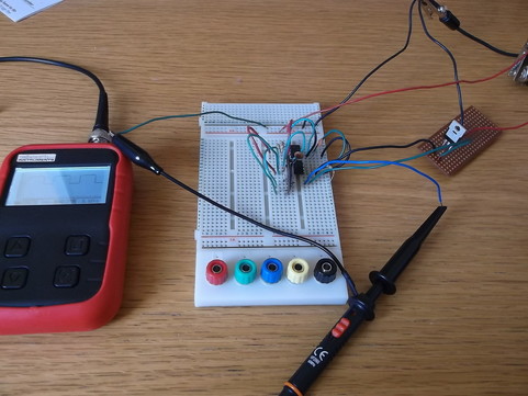
Here the MOSFET can be seen connected into the circuit driving the heater/fan unit.
At the time of the testing the fan/heater unit has not been modified to separate the drive to the fan and heater element. In the final implementation the PWM circuit will drive the heater element and the fan will be driven from the 24V supply directly.
Although all the wiring with crocodile clips does not look nice it takes me back to my very early days experimenting with electrical circuits at home and at school.
More information to follow soon.....
