Background
Like many people of a similar age i was part of the 'ZX Generation ' that learned hands on about computer hardware and software on the Sinclair ZX81 home computers. I had plans to control the world from my ZX81 so when Maplin started producing add on boards i had to get one. In the end i purchased a motherboard and two I/O boards. Being a student at the time i did not have the money to buy all the components for the two I/O boards so i purchased enough to populate one and would complete the second board when i had the first running and more importantly the money to buy the components! Unfortunately i never got round to completing the system because end of year exams were looming, job applications had to be completed and interviews had to be attended and so i never did find out if it would work. I started working as an Electronic Design Engineer developing banking equipment and at the time the ZX81 seemed less important and i did not seem to have much spare time.
Recently a friend and i were reminiscing about the 'ZX days' and he asked me if i had ever got the I/O board working. That got me thinking there was some unfinished business lurking somewhere in a cupboard so i set about finding it. I had a good idea where i had stored it and there it was still in the original 'Jiffy Bag' it was delivered in as a kit of parts. I unpacked the parts and took the photographs on this page.
I plan to complete the assembly and test the boards on the ZX81 and see if after over 30 years it all still works!
I must have planned to take over the world because i purchased two I/O boards with a total of 48 input/output lines!
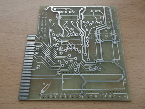
This photograph shows the second unpopulated board which has been lying around for the past 33 years.
It was purchased from Maplin Electronics in the UK via mail order as in those days they only had a 2-3 shops around the country.
If all goes well i plan to purchase the components and complete the assembly of this board.
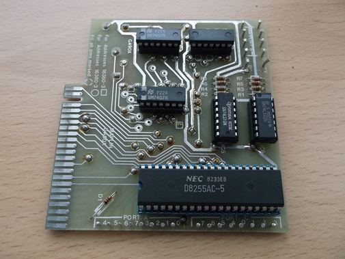
This is the assembled board. All of the components are still readily available.
Some of the TTL chips provide the address decoding for the 8255 VIA (Versatile Interface Adapter) so that the control bytes can be written to the control register and the contents of the A,B & C ports read from/written to.
The remaining TTL chips provide buffering of the 8255 outputs to protect them from being overloaded.
The 8255 can be configured to provide the required input/output lines on its ports depending on the value written to the mode control register.
I also purchased a motherboard so that i could use up to three boards in the series that Maplin produced. They also sold a sound generator board, Modem and high resolution video board.
I have a vague recollection that i ordered the wrong number of edge connectors, forgetting that i also needed one to connect onto the rear of the ZX81!
The 16KByte RAM pack connected onto the right hand end of the motherboard.
So in order to complete this project the first task i have to do is to get one or more edge connectors.
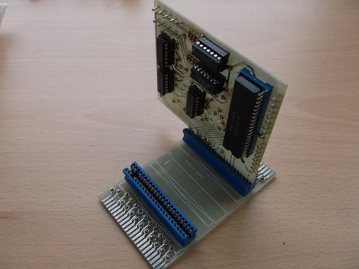
This photograph shows how the system assembles together.
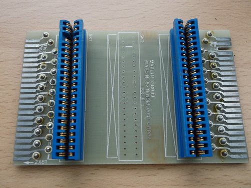
The motherboard should have an edge connector soldered onto the contacts at the left hand end of the board which in turn will connect to the edge of the ZX81 motherboard.
The 16KByte RAM pack connected onto the right hand end of the motherboard.
The edge connectors are still available but not in the 23 way version but in larger sizes that can be cut down to fit.
The edge connectors will be purchased and soldered in place before the boards can be tested. Further information to follow in the near future......
Update: 19th March 2015
Update: 19th March 2015
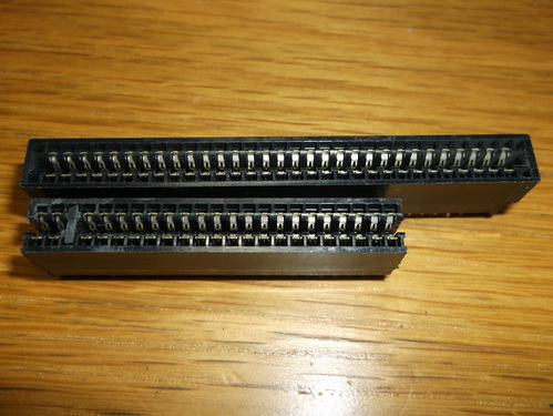
The only edge connectors easily available were 31 way and i need 23 way types. The connector was carefully cut down to 23 contacts using a fine tooth small hack saw. The end was then cleaned up with a fine file to give a clean finish.
The third contact on each side of the connector was carefully removed using fine nosed pliers to create a space for the 'key'.
A 'key' piece was made using the end cap of the the other end of the connector which was carefully cut off so that the connector length would be correct to fit into the rear of the ZX81. The cut off piece was filed down to the correct size to fit the key location.
The original and modified connectors are shown in this photograph with the key piece installed in contact location 3 as viewed from the left hand end of the connector.
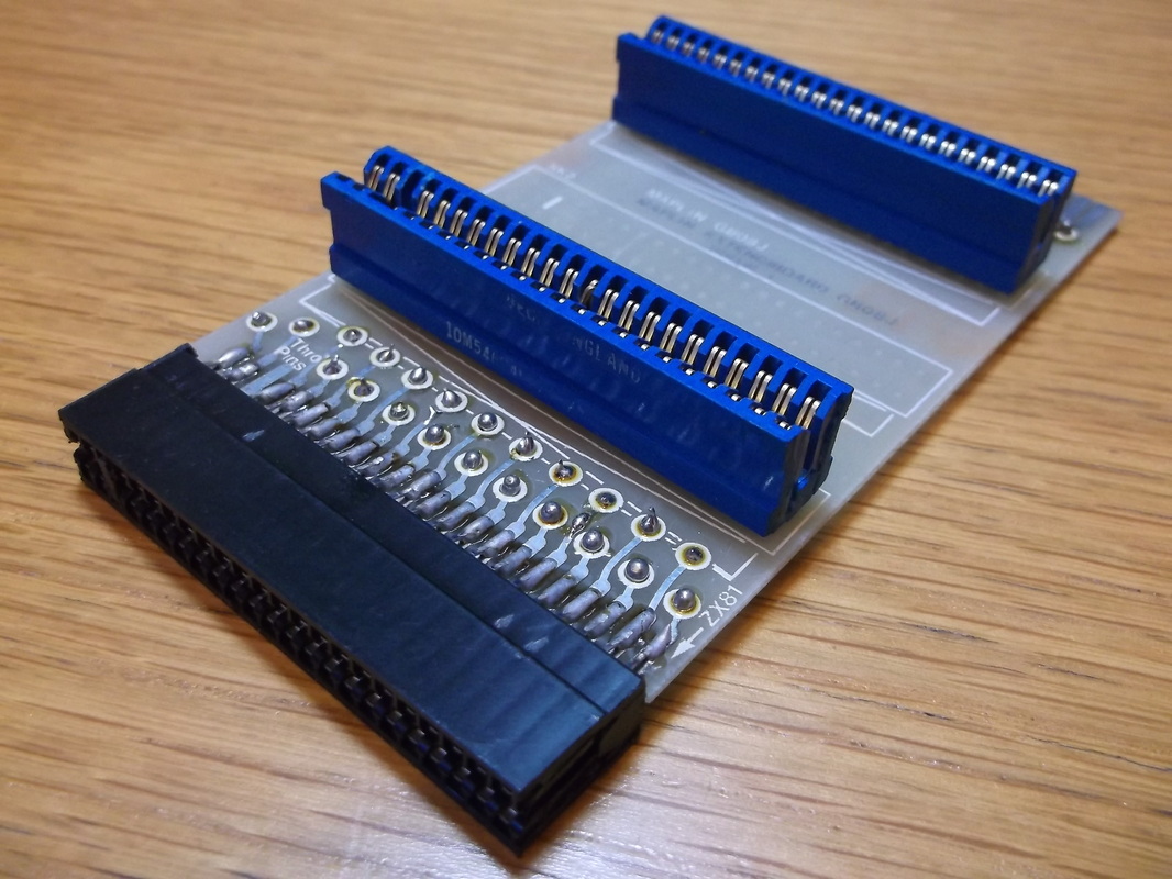
The modified connector was soldered to the edge connector trying to keep the circuit board centered between the two rows of pins. A few pins at each end of the connector were soldered first to align the connector on the PCB and secure it in place. The rest of the pins were then soldered in place.
|
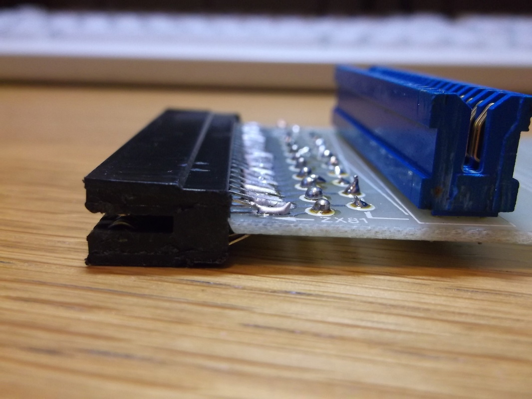
This picture shows the mounting of the edge connector on the Extender Board PCB. Although there are over thirty years between the time the board was first soldered and now, unfortunately the quality and consistency of my soldering has not improved! The alignment of the connector on the rear of the ZX81 was checked and seemed good.
|
Update: 21st March 2015
The completed extender board was installed onto the rear connector of the ZX81. The ZX81 was switched on and it was tested to ensure that there were no problems with the board itself. The ZX81 ran normally. The ZX81 was switched off and the I/O board was plugged into one of the sockets of the extender board. The ZX81 was switched on. The ZX81 did not start up correctly. After over 30 years of lying in storage i was not surprised by this.
I repeated the following tests in an attempt to isolate the problem, each time switching the ZX81 off and on between tests.
1. Remove the 8522 interface chip and retest. ZX81 hangs.
2. Remove 74LS02 TTL chip (IC1). ZX81 Hangs.
3. Remove the 74LS30 TTL chip (IC2). ZX81 hangs.
4. Remove the 74LS10 TTL chip (IC3). The zx81 boots normally.
(n.b. These are the chips i thought i was removing. I was removing them on the basis of their function and component number, e.g. IC2, not the chip marking.See below for further details.)
I decided i would add the chips back one at a time(without the 8255 inserted) and try to find out exactly when the problem occurs.
I decided to re-insert the 74LS10 (IC1) chip first only to find that when i checked the markings on the chip it was a 74LS07 and the 74LS10 was already in the circuit board in location IC5!. (Refer to the heading photograph.) This would explain a lot indeed! I removed all chips from the PCB and ensured that all the correct chips were present. I then inserted each chip into the correct location ensuring the correct orientation.
I inserted the I/O board into the extender board(without the 8255) and powered up the ZX81. It powered up normally. I switched the ZX81 off again and inserted the 8255 into the I/O board and retested. The ZX81 powered up normally! This was great news. Of course it was still possible that some of the chips had been damaged when they were inserted into the wrong sockets.
I ran a simple test program supplied with the I/O board and used a multi-meter to check the output of the 8255 chip directly at the input to the 74LS07 output buffer chips. The outputs toggled as expected. So the board was working after all those years in storage.
The mystery remains as to how the chips were put into the wrong sockets? I do not know if i still have the original circuit diagram and assembly instructions supplied with the board but the ones i downloaded a few weeks ago when i decided to start looking at this project again match the circuit board i have. Unfortunately it is a mystery i will probably never solve.
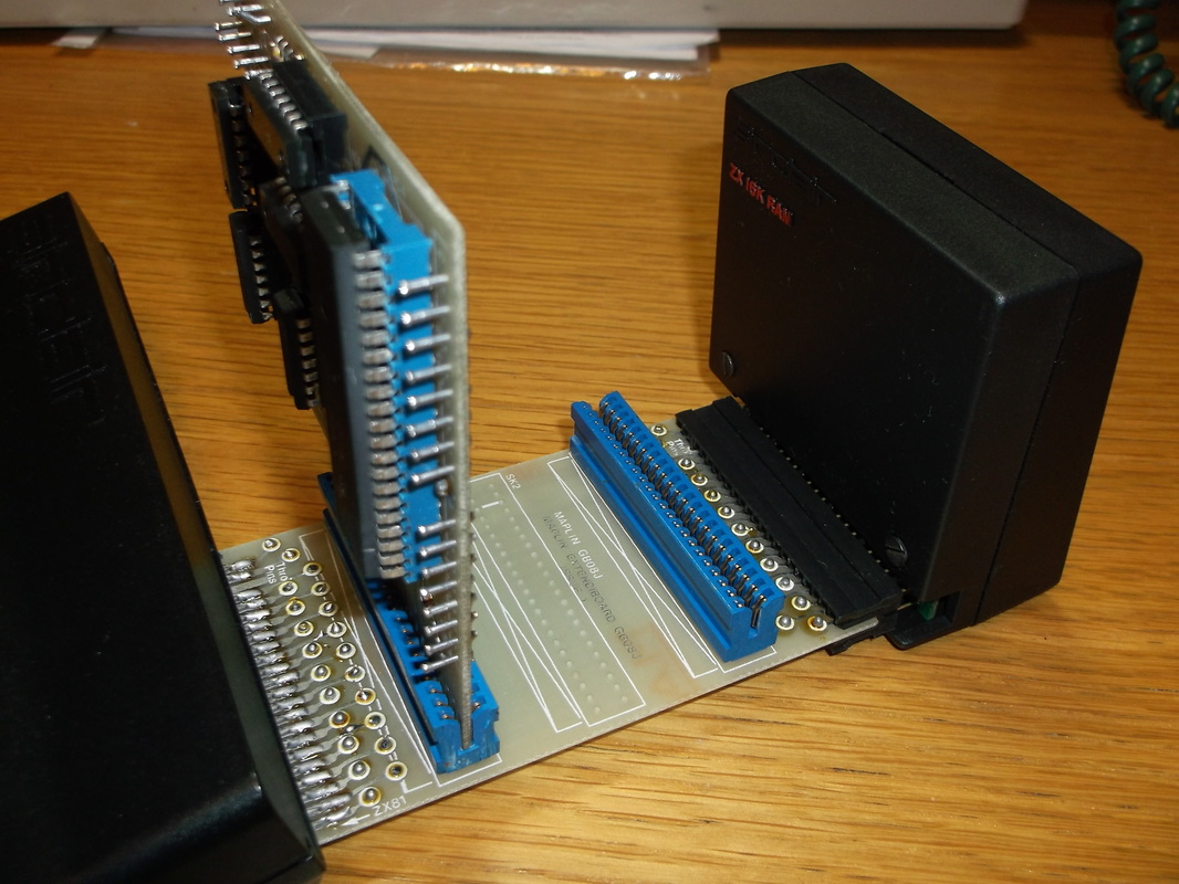
This photograph shows the I/O board installed into the extender board which in turn is plugged into the rear connector of the ZX81.
|
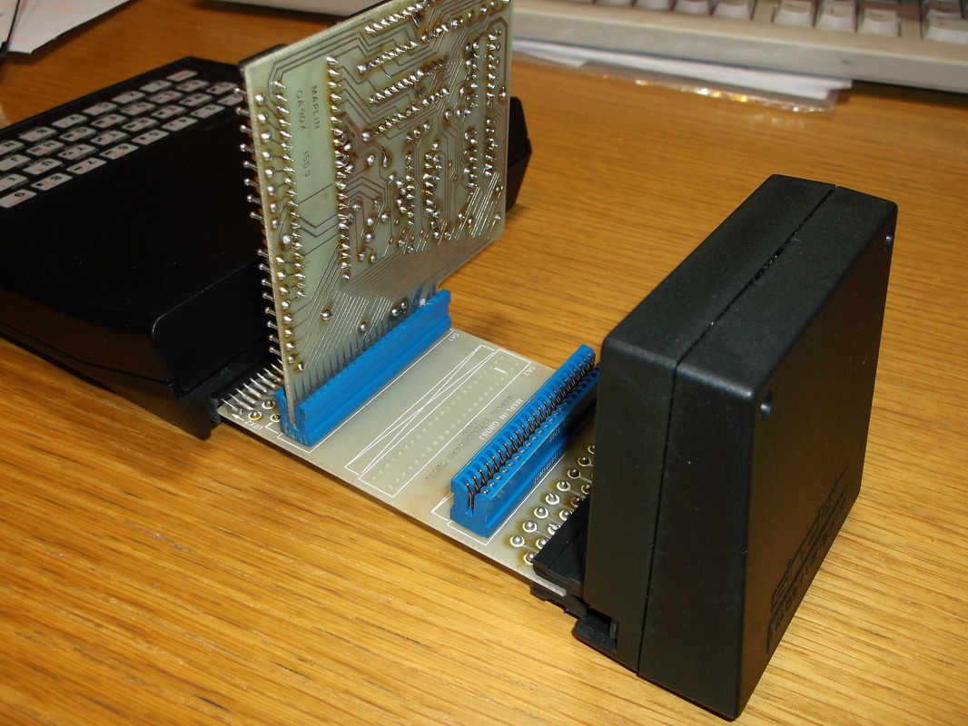
This photograph shows the reverse angle of the the I/O extender board into which is plugged the ZX81 16KB memory expansion pack.
|
I plan to build a simple circuit with LED's or a seven segment LED display to test the operation of the I/O board and to take some photographs of the results for this website. More details to follow......
