Background
I had been looking for a sturdy DC motor for a number of projects for some time. The prices of a brand new motor of the size and power i was looking for were quite extraordinary, of the order £60-£70. I investigated getting one from a car scrap yard but even they were looking for £20-£25 for a second hand unit. I happened to be in the Scottish Borders on the weekend of the Jimmy Guthrie Memorial Run in 2014 in the village of Denholm. Along with all the vintage cars and motorcycles there was a car boot sale and spare parts market on the village green. I purchased this windscreen motor for £3. It was old and dirty but it was solid and could be easily dismantled to be repaired or modified. The same stall had more modern smaller motors and mechanisms from windscreen wiper systems and electric window systems but they were not easily dismantled nor modified.
I needed the motor to have the following characteristics:
I needed the motor to have the following characteristics:
- To operate from 12V DC.
- To be reversible.
- To allow access to internal components for repair or modification.
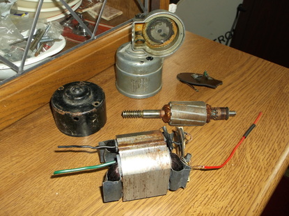
As i did not know if the motor worked or not when i purchased it the first thing to do was test it. I connected the red wire to the +ve and the green wire to the -ve terminal of a 12V battery. The output shaft rotated so that was good news. I reversed the terminals and the motor turned the same way. This confirmed what i was already pretty certain of that the motor had a wire wound stator rather than permanent magnets. A little research revealed that the car industry did not trust the reliability or longevity of permanent magnet motors until well into the 1980's so wire wound field motors were common until then. After an initial test i used cleaning solvent to remove all the dirt, grease and oil from all the external casings. Then i dismantled the motor to inspect all the component parts. In this picture the following parts can be seen, main motor housing with gearbox housing and right angle crank drive, electrical contact plate, armature with worm drive, motor end housing, stator and field winding.
After dismantling the motor all the parts were cleaned and surface rust brushed off. Then all parts were oiled with machine oil to prevent further corrosion.
I was able to examine the windings and connections and concluded that the motor was a shunt wound DC motor. In order to convert the motor into a reversible one i had to separate the stator/field and rotor windings and bring them out of the casing to separate sets of connections. I successfully completed this and then re-assembled the motor.
I connected it to a 12V DC source and tested the motor only to find that the motor moved just a few degrees and then stopped. I rechecked all the connections but each time the test result was the same.
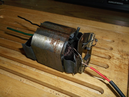
I dismantled the motor again and started to carefully examine the stator windings again. By using a plastic tool i was able to move aside the thin windings of wire and locate much heavier gauge wire wound on the sator below the thin wire.I was able to trace the wire connections and found the motor was not a pure shunt or series type but a 'short shunt compound wound' motor, a cross between a shunt and series wound type.
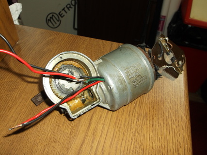
I modified the wiring to allow separate connections for the stator windings and the rotor windings to be brought out of the case of the motor.
I connected up the motor to a 12V DC source and tested its operation. This time it rotated as expected. I reversed the connections on the stator/field winding and the motor rotated in the opposite direction as expected.
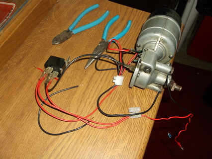
In this picture the motor is connected to an external automotive relay to allow the 'self parking' function of the motor to be tested. The motor gearbox has a sliding contact installed which was part of the self parking feature. The motor is wired so the self parking switch is in parallel with the switch that controls the power to the relay coil. When a short pulse is provided to the relay field coil the relay contacts close and the motor rotates closing the self parking switch contacts in the motor. When the pulse is removed the relay remains energized and the motor rotates until the self parking switch reaches it's home position and disconnects power to the relay and as a result the motor. This simple set up ensures the motor output crank makes only one revolution.
If instead of a pulse the power to the relay coils is maintained the motor will rotate continuously and when the power is removed from the relay the motor will stop within one revolution of the power being removed.
I have a lot more work to do with this and i will update the website when it is complete......
