Background
I have developed a number of drive circuits based on LM339 and LM393 comparators using current sensing techniques to generate an oscillator circuit that would drive an LED Lamp. This was successfully achieved driving LED lamps up to 7 watts. These circuits gave very good performance but because of the nature of the drive circuit they were not getting the maximum out of the LED lamp.
I decided to borrow some techniques from switch mode power supplies and develop a push-pull circuit that would get a lot more performance out of the LED lamps. This technique required developing a push-pull transformer, a circuit capable of driving the push pull transformer and the software to drive the hardware.
I decided to borrow some techniques from switch mode power supplies and develop a push-pull circuit that would get a lot more performance out of the LED lamps. This technique required developing a push-pull transformer, a circuit capable of driving the push pull transformer and the software to drive the hardware.
A few ferrite rings that were about 30 years old were to hand and h
I had some ferrite toroids that had been lying around for over 20 years. I decided to use these but at the lowest performance level to avoid damage to the drive circuit.
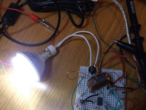
This picture shows the drive circuit in the bottom right hand corner of the breadboard together with another un-related project to the left. The drive circuit consists of two NPN transistors driving the two halves of the primary side of the transformer.
To initially prove the concept the transistors were driven by two output bits of an Arduino. Using the Arduino it was possible to drive the primary winding at approximately 13KHz.
The number of turns for the primary and secondary windings were calculated using the standard equations for transformers.
I had some ferrite toroids that had been lying around for over 20 years. I decided to use these but at the lowest performance level to avoid damage to the drive circuit.
This picture shows the drive circuit in the bottom right hand corner of the breadboard together with another un-related project to the left. The drive circuit consists of two NPN transistors driving the two halves of the primary side of the transformer.
To initially prove the concept the transistors were driven by two output bits of an Arduino. Using the Arduino it was possible to drive the primary winding at approximately 13KHz.
The number of turns for the primary and secondary windings were calculated using the standard equations for transformers.
Initially the transformer was used to drive a 4W LED lamp. The drive transistors got a little hot and as the ZTX651 is in an E-Line package it is not easy to attach a heat sink especially when the circuit is on a breadboard. In later testing the 4 W LED lamp was replaced by 1.6W and 2.3W LED lamps to reduce the heating in the drive transistors.
The Arduino is a really useful device for these sort of prototyping projects as generating pulses is very simple using the Arduino 'C' like programming language.
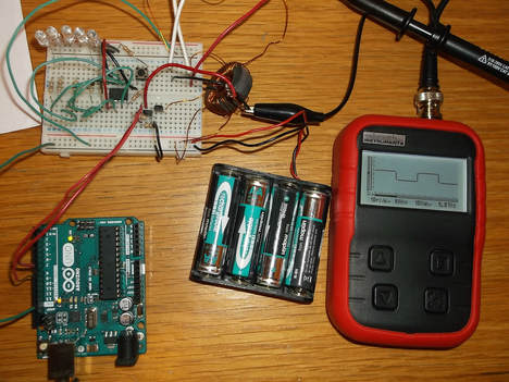
Here the drive circuit is being powered from a battery pack and driven from the Arduino.
The oscilloscope shows the pulse stream of one of the drive channels.
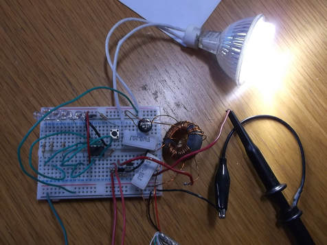
In this picture the push-pull transformer wound on the toroid can clearly be seen driving the LED light via a full wave bridge rectifier. Two 0.1 Ohm resistors have been inserted into the primary and secondary circuits so that the current wave forms could be checked with the oscilloscope.
The circuit is driving a 2.3W LED lamp.
A PIC 12F675 micro controller program was written in a mixture of 'C' and assembler language using the Microchip MPLABX development environment.
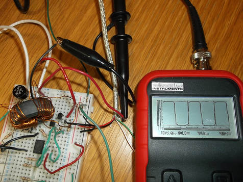
By using the PIC 12F675 it was possible to increase the frequency of the pulse stream to 20KHz.
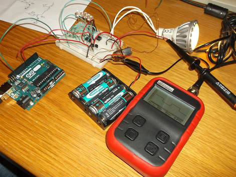
The oscilloscope shows the waveform on the output of the secondary winding of the transformer showing the +/- 12V swing of the voltage with the slight pause at the zero volt crossing clearly showing the 'dead band' programmed into the PIC to prevent short circuits across the power supply.
This picture shows the circuit driving a 2.3W, 12V LED lamp using the PIC 12F675 to drive the transistors.
A full wave bridge rectifier was used on the secondary output to allow both AC and DC LED lamps to be tested.
The AC LED lamps can be driven directly from the output of the secondary winding.
The transistors showed only slight warming when driving this load.
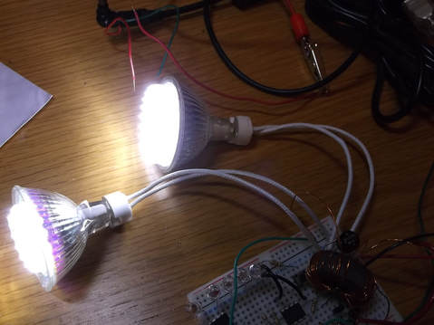
This picture shows the circuit driving a 2.3W, 12V and 1.6W, 12V LED lamp simultaneously using the PIC 12F675 to drive the transistors.
The transistors showed only slight warming when driving this load.
