Background
Over a number of years my parents had an ongoing problem with the drains taking water from the bathroom , particularly the bath and shower. The water seemed to take a long time to drain away and occasionally it appeared that water would come back up the drain leaving debris around the drain of the bath and shower. My parents purchased various plungers over the years to keep on top of the problem and used soda crystals down the drain with hot water to try to keep it clear.
In May and June of 2013 there were a few heavy rain showers and water came back up the bathroom shower drain, not a huge amount but enough to cause concern. I contacted Scottish Water, they arrived the following day and could find no problem, stated that the main street sewer was flowing freely and more worryingly said they could not find any drains on my parents nor neighbours property with whom they share the drains that they could inspect.
A few months later in October 2013 there was a heavy rain shower and i went out side to watch it. While standing in the path i heard a strange gurgling noise which came from the top of the guttering down pipe. I tapped the cast iron down pipe and it sounded dull indicating it was full. That was worrying. The following day i found my parents neighbour digging around the base of a bush. He said that water was coming up out of a drain flooding his garden. He turned on a kitchen tap and water gurgled up out of the drain. I was quite shocked because i could not actually see the drain but there was an awful lot of water coming out of it! After a bit of digging down approximately 8-12 inches a concrete slab was exposed which was lying at a strange angle. The water was gurgling out from under the slab.
This helped explain a number of things that had happened in the previous couple of years.
1. The gutters overflowing during heavy rain showers.
2. The path appearing to flood and the water taking a long time to drain away.
3. Strange patterns appearing in the soil of the neighbours garden.
The patterns gave the impression that a large amount of water had flowed and settled on the surface.
4. Water in my parents shower taking a long time to drain away.
5. Water coming back up the shower drain during heavy rain showers.
None of these problems had occurred in previous years.
Before starting work the blockage was removed and the area around the drain vent cleared to avoid any further problems with debris falling into the vent. I set up a small video camera on the end of a cane and connected this to a portable TV. The video camera has built in infra-red LEDs to allow use in low light conditions. The camera was lowered down the drain vent and turned so that the view up the various branches of the drain could be inspected. The pipes were completely clear apart from a surface lining of grease/fat which has probably built up due to the periods when the water had backed up in the pipe and any liquid grease/fat condensed on the cold surface of the pipe.
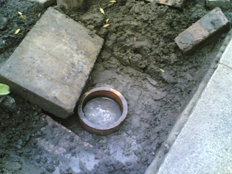 Original drain vent pipe exposed.
This is the top of the vent pipe after the soil that had collapsed into the chamber had been removed. Some of the bricks of the chamber have also been removed as they were lying at a steep angle. At some point in the past my parents neighbour had made the slate cap seen in the photograph. When the soil level was raised and the vent covered the soil which fell into the chamber created a seal over the vent causing a siphoning effect in the drain reducing the ability of the water to flow away. The slate itself would severely restrict the air movement in the drain causing reduced drain performance.
The original drain chamber was poorly built. There was no suitable foundation. What passed as a foundation consisted of some mortar placed onto the soil and the bricks placed onto the mortar.The top layer of bricks were then laid on these. Over the years, settlement of the soil and digging caused the chamber to sink on one side until the stone slab cover was resting on the vent opening and then fell off, finally the entire structure was buried under soil during garden renovations. It was only a matter of time before problems would occur.
The original drain chamber was poorly built. There was no suitable foundation. What passed as a foundation consisted of some mortar placed onto the soil and the bricks placed onto the mortar.The top layer of bricks were then laid on these. Over the years, settlement of the soil and digging caused the chamber to sink on one side until the stone slab cover was resting on the vent opening and then fell off, finally the entire structure was buried under soil during garden renovations. It was only a matter of time before problems would occur.
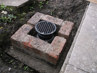
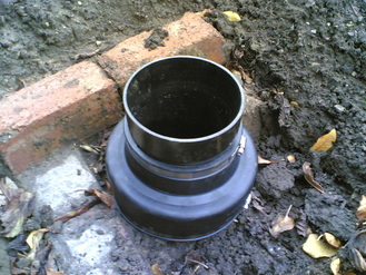 Vent pipe with Flex-Seal adapter and riser fitted.
After a great deal of investigating i came up with the solution shown in this picture. A Flex-Seal adapter is used to connect the top of the vent to a plastic riser into which a grilled drain cap is fitted. A bushing is fitted internally to prevent lateral movement of the riser and drain. The objective was to not interfere with the current construction of the vent. A builder had suggested cutting off the socket of the clay pipe so that a cheaper coupling could be used but i decided not to take this approach as it increased the risk of damage to the pipe. The proposed solution provided a solid mounting for the riser and raised the level of the vent above the current ground level.
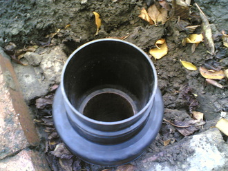 Vent pipe showing riser seated on clay pipe.
This photograph shows how the riser slips inside the Flex-Seal adapter and sits on the top of the clay pipe. This ensures that the riser will not slip down the inside nor the outside of the clay pipe as could have happened if the end of the clay pipe had been cut off.
The brick remains of the vent chamber can still be seen around the base of the vent opening.
The brick remains of the vent chamber can still be seen around the base of the vent opening.
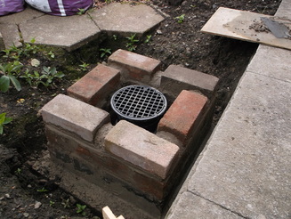
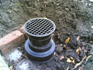 Vent pipe with all parts fitted.
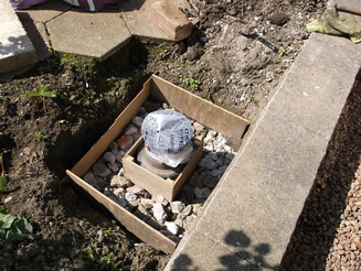
This photograph shows the modified top of the vent pipe with all parts installed.
The vent pipe was left like this for six months and regularly inspected to ensure the drain was operating correctly. This could be tested by placing a plastic bag over the top of the drain and sealing it around the top of the vent pipe. When it rained the water running into the drain from the guttering down pipes forced air out of the drain up the vent pipe and inflated the plastic bag.
The vent pipe was left like this for six months and regularly inspected to ensure the drain was operating correctly. This could be tested by placing a plastic bag over the top of the drain and sealing it around the top of the vent pipe. When it rained the water running into the drain from the guttering down pipes forced air out of the drain up the vent pipe and inflated the plastic bag.
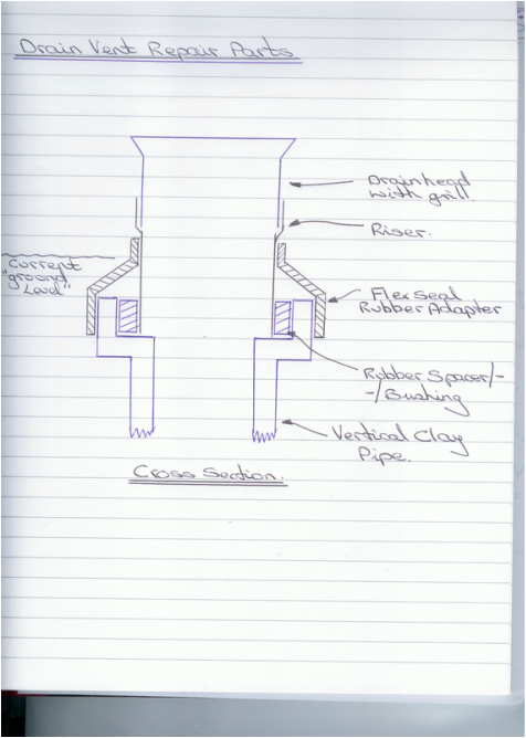
This picture shows a cross section drawing of the drain components as assembled in the photograph above.
This shows the relative positioning of components in particular the rubber bushing/spacer which is not visible in the photographs but it is very important in keeping the assembly stable.
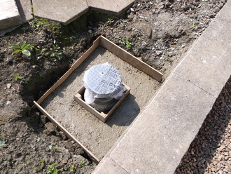
 Shuttering fitted and hard core in place.
As soon as the weather improved and it was confirmed the drain was working correctly work started to build a new chamber to protect the drain.
All the old bricks were removed and the soil dug away to create a useful working area. The old bricks were cleaned up removing the old mortar and prepared to be reused where ever possible. Other bricks of the same size lying around the garden were collected and cleaned up if required. Measurements of width and height suggested that 18 bricks in total would be needed.
The soil at the base of the new chamber was leveled and compacted. Old bits of concrete from fence post bases were broken up and together with stones and gravel from around the garden were used to create a compacted base for the concrete. Some off cuts of wood and plywood were used to make some shuttering to contain the concrete while it set.
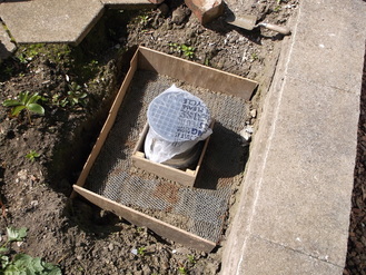
 Small core layer added over hard core.
After the larger rocks and broken up concrete were compacted into place a layer of smaller gravel was laid on top and compacted into place.
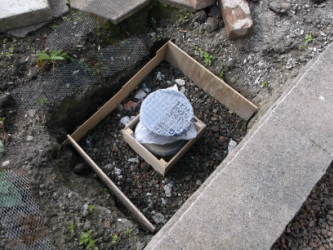
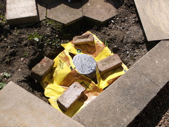
A polythene bag was placed over the vent opening and secured in place with string to ensure that as little debris as possible went down into the drain.
The purpose of this vent was very well demonstrated each time water passed through the drain as the polythene bag would inflate as water pushed air out of the drain and up through the vent.
 First layer concrete installed and reinforcing mesh added.
Two bags of ready mixed quick drying concrete were used to create the base of the chamber.
After mixing with water these give approximately 30 minutes of working time before they begin to set.
In this picture the first layer of concrete has been laid on the gravel base and leveled. A layer of galvanized building reinforcement mesh has been laid on top of the first layer to provide some additional strength to the concrete.
 Top layer concrete added over reinforcing mesh.
The second layer of concrete was then mixed and immediately poured on the top of the first layer to try to ensure they would set as one continuous block.
The top was smoothed out and leveled as best as was possible.
 Cement bags recycled to protect concrete from sun and rain.
As it was a warm sunny day when the concrete was laid it was covered with polythene to protect it from the rain forecast later that evening and also to stop it drying out too quickly in the direct sun light.
The polythene is not in contact with the setting cement. They are in fact the cut up bags the cement was supplied in.
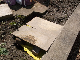 Marine ply panels to keep sun and rain off concrete.
Some spare pieces of plywood were used and covered with more polythene to allow any overnight rain water to run off so that it would not get to the concrete and damage it before it could set completely.
 First layer of bricks in place.
The concrete base was left for a week to fully set.
The cleaned up recycled bricks were laid in place before mixing any mortar to get a good feel for their final positions. As i am not an experienced bricklayer i used chalk to mark the positions of the bricks on the concrete base and used a piece of wood(as seen in the photograph) to ensure a good line up between the bricks.
One bag of ready mixed mortar was used to lay the bricks preparing the mortar in batches to avoid wastage due to my slow brick laying.
 Second layer of bricks in place.
The second layer of bricks were laid immediately after the first. The gaps seen between the bricks were too small to make cutting a brick to fit so they were filled with mortar gradually so that it would not fall out as it was applied.
The bricks were left over night to allow all the joints to dry and to see if the large gaps filled with mortar had been a success.
The bricks were left over night to allow all the joints to dry and to see if the large gaps filled with mortar had been a success.
 Third layer of bricks in place showing ventilation gaps.
The final third layer of bricks were laid. These were slightly smaller than the bricks used in the lower layers. This ensured that the drain chamber with its capping slab on top would be lower than the adjacent wall seen in the bottom right hand corner of the photograph and also left gaps to allow air to enter and exit the vent which is its primary purpose.
The gaps between the top layer of bricks were partially filled with mortar and given a curved shape so that soil and water at the sides would tend to roll out again.
Great care was taken at this point to ensure that the top layer of bricks were level so that the capping slab would not rock.
The capping slab was temporarily fitted to check that it was a good fit.
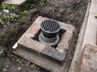
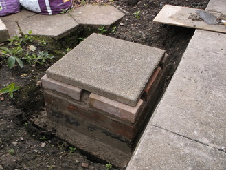 Chamber complete with temporary capping slab in place.
A temporary capping slab was fitted to ensure that the surface was level and then left for a week to allow the mortar to dry.
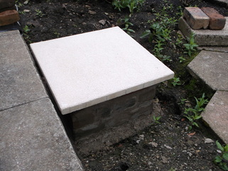
After a week the final capping slab (600mm x 600mm) was installed. The soil surrounding the chamber was put back after approximately two weeks which allowed all the mortar to fully dry out.
This picture shows the chamber two months after completion. When it was first inspected the inside had become home to dozens of snails and slugs so the vent openings around the chamber were fitted with stiff galvanized wire mesh to prevent them getting in and using the chamber as a base from which to set out and devastate the nearby plants. The mesh is just visible beneath the top of the slab in the lower half of the picture.
To date(October 2014) the mesh has done it's job and the snails and slugs have not come back.
