Background
From the very start of the design of the scooter port I wanted the gates to be a bi-folding design so as to save space. By using the bi-folding gates the length of the port can be shorter than if the gates were of a standard non folding type. More specifically the gates were to automatically fold when they were opened and unfold when they were closed. By implementing an automatic folding mechanism, if the gates were to be left open or opened by a strong wind the gates will automatically fold and not hit the rear of the scooter as long as the scooter was parked sufficiently far from the entrance.
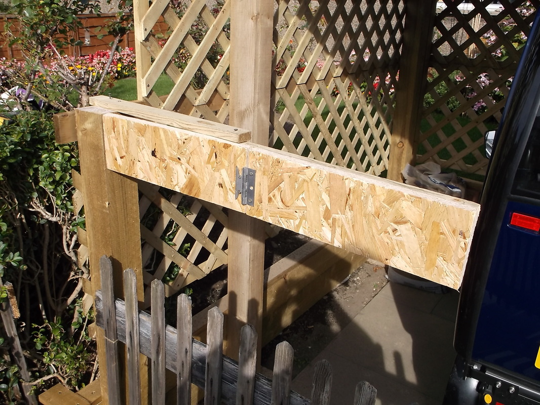
Prototype mechanism fully closed.
|
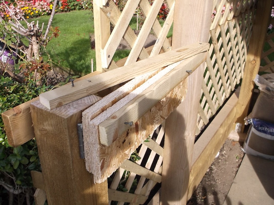
Prototype mechanism partially open.
|
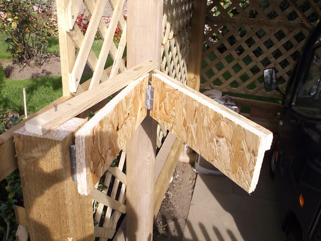
Prototype mechanism fully open.
|
I constructed a very crude prototype using some old hinges and offcuts of wood to simulate one pair of bi-folding gates. From this i was able to confirm that the mechanism would work as i wanted it to and to allow me to verify some initial measurements and calculations i had already done. After that was completed i was able to start on the cosmetic appearance of the gates.
to As I had some trellis left over from enclosing the scooter port i decided to use this as part of the construction of the gate. This had three advantages:
1. It is lightweight and would keep down the overall weight of each panel of the gate. This would minimise the stress on the hinges and posts as the entire weight of the gate is cantilevered from the hinge at the side post.
2. It stiffens the wooden frame of each panel while keeping down its weight.
3. It will allow wind to pass through thus reducing the wind loading on the panels reducing the possibility that they will be damaged under a high wind load.
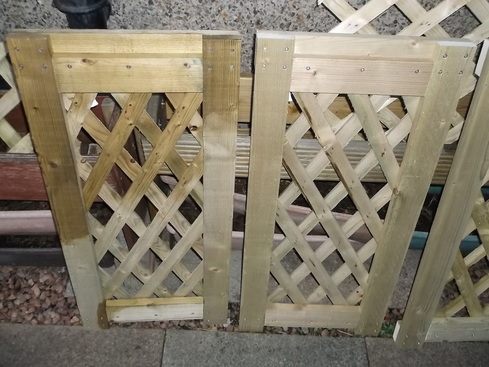
The frame was made from sections of 75 mm x 22 mm pressure treated wood secured together with 4 mm x 20 mm stainless steel self drilling, self tapping screws. It was essential to take care to ensure that the panels were squared up as near perfect as possible as any errors would accumulate when the panels were connected together.
1. It is lightweight and would keep down the overall weight of each panel of the gate. This would minimise the stress on the hinges and posts as the entire weight of the gate is cantilevered from the hinge at the side post.
2. It stiffens the wooden frame of each panel while keeping down its weight.
3. It will allow wind to pass through thus reducing the wind loading on the panels reducing the possibility that they will be damaged under a high wind load.
The frame was made from sections of 75 mm x 22 mm pressure treated wood secured together with 4 mm x 20 mm stainless steel self drilling, self tapping screws. It was essential to take care to ensure that the panels were squared up as near perfect as possible as any errors would accumulate when the panels were connected together.
I had 5 pieces of trellis left over from the main scooter port construction all of slightly different sizes. Unfortunately none of them was the correct dimensions to fit or to be cut down to fit.
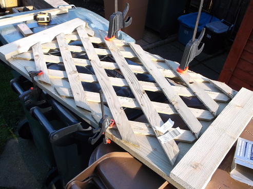
However i was able to 'squeeze' the trellis into the correct dimensions and then secure it to the rear of the gate panel using stainless steel screws.
In this picture the trellis has been squeezed to reduce its width forcing its vertical height to increase and fit the panel without having to cut or trim it. The trellis was held in place with quick release clamps while the screws were inserted.

After struggling to install the trellis on the first panel as it seemed i required 4 or more hands!, i came up with the solution shown in this picture.
Set up the quick release clamp and apply the pressure to change the shape of the holes until the length and width of the trellis is the desired size.
The screws can then be used to secure the trellis to the panel.
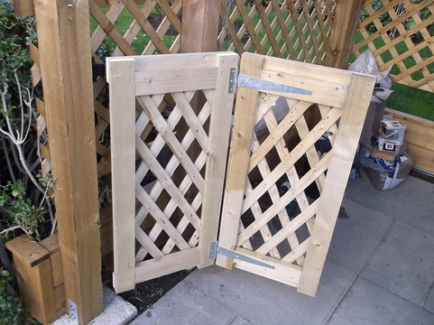
Here the two halves of one side of the gate have been connected together using medium duty T-Hinges.
The entire assembly is mounted on the gate post using heavy duty band and hook hinges. These are very simple, effective and robust in this type of application.
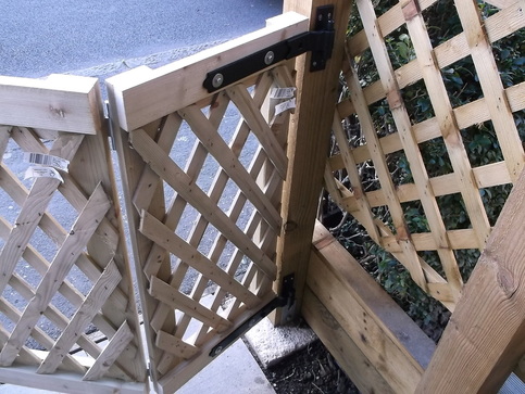
Here the mounting of the bi-folding gates on the gate post can be seen.
The hook and band hinges are secured to the rear of the gate panel with hex head stainless steel coach screws.
The dimensions of the gate were designed from the outset so that when the gate is open and folded it fits into the space between the gate post and the scooter canopy support post ensuring that the entrance is as wide as possible with as little intrusions as possible.
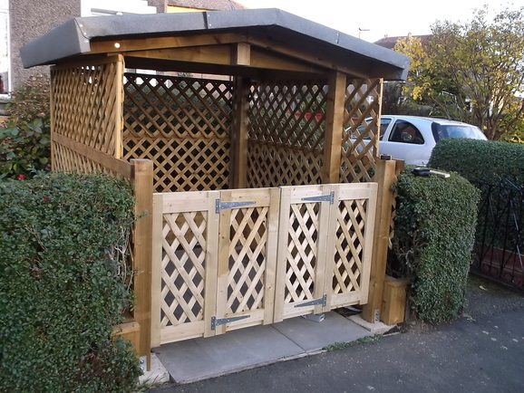
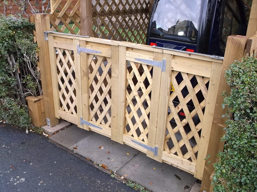
Here the four panels can be seen mounted in position before the wood oil was applied.
The automatic folding and locking mechanisms still have to be installed.
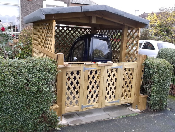
Here the gates have received their first coat of oil and after a few days they are starting to match the colour of the rest of the scooter port.
There are various pieces of wood on the top of the gates. These are being used to refine the operation of the self folding mechanism and also to act as a simple temporary locking mechanism. These will be replaced with the permanent mechanism in the near future
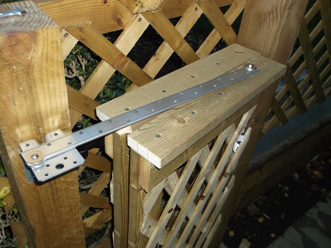
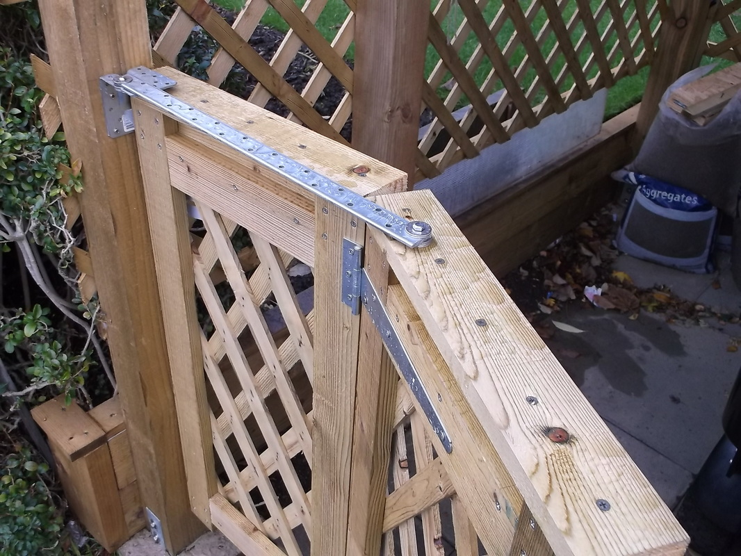
 One half of folding gate mechanism in closed position.
I had identified possible parts for the automatic folding mechanism some time ago. I had considered two options:
1. Using wooden parts.
2. Using metal parts.
Some experimenting with wooden parts outlined earlier in this page showed that the tolerances required to make the mechanism work were not easily achievable with wood and would be much bulkier than that possible by using metal parts.
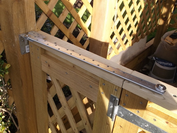
I chose to use parts that were already available and were originally intended to be used in the building and construction industry to hold building structures such as floors and roofs together. They are a bit like giant, very strong Meccano pieces.
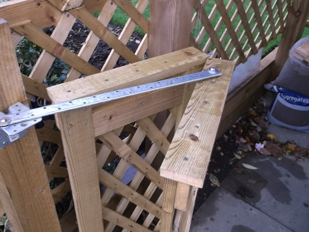
The mechanism consists of a right angle bracket mounted on the gate post. The folding arm is made from a piece of stiff perforated galvanised steel. The folding arm is secured to the right angle bracket and to one of the halves of the folding gate as shown in this photograph. Stainless steel washers were used as spacers where required to align the components and allow the parts to rotate against one another smoothly.
The dimensions of the folding parts were selected so that there was a built in "locking" mechanism in both the open and closed positions. This gives the gates a stiffer stance in the fully open or closed position and means that they will not move when there is a strong wind.
Before the folding mechanism was installed on the gates wooden caps were attached to the four half panels to provide a better cosmetic finish and to provide a means of securing the mechanism in place.
Left side gate in open position.
|
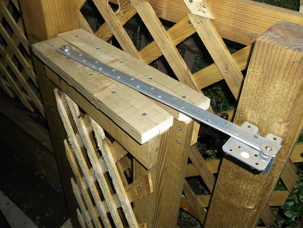
Right side gate in open position.
|
Click on any one of the four pictures below to view a larger version.


The pictures below show the completed gates with the folding mechanism and locking mechanism installed.
In this picture the scooter, charger, scooter port and gates have been in regular use for two months. The very low profile of the folding mechanism arm can just be seen here.
|
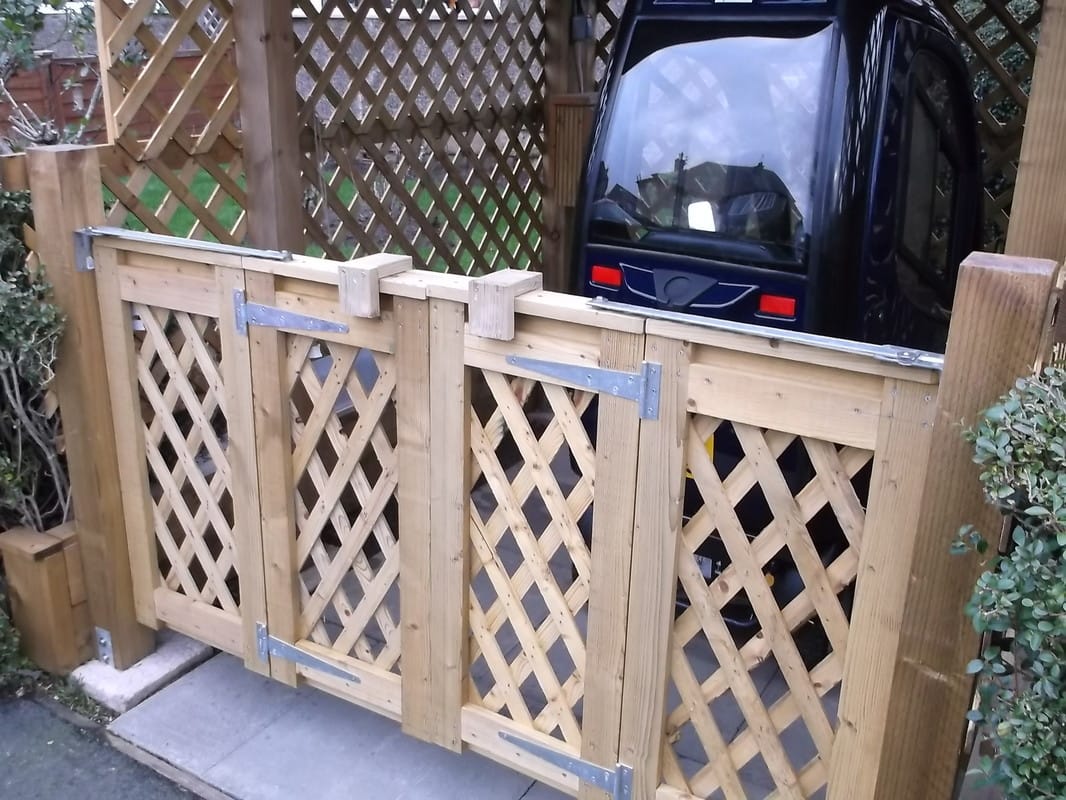
In this picture the very simple locking mechanism can be seen across the middle of the gates. A piece wood hidden on the rear of the gates stops them from being blown open in the wind. The wooden bracket simply lifts off to allow the gates to be opened.
|
