Introduction : Commercial Ward Propagator Repair
I have become more and more frustrated at the throw away culture particularly in the electronics industry. While i fully understand that items may be beyond economic repair, i.e. component repair and labour cost greater than complete unit replacement, i still find it very difficult to discard equipment that simply requires a few pounds or even pence to repair together with some time and effort.
Approximately 20 years ago my Father purchased an electric propagator. After a short time it failed. It was replaced by the manufacturer but sadly it also failed after less than a year. The manufacturer is no longer in business, surprise,surprise! For many years my Father used the unit as an unheated propagator. After a run in with another propagator manufacturer over the failure of a very expensive unit where the thermostat failed after just over two years i decided to try to repair it as well as my Father's propagator.
 New control box attached to propagator base.
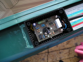
After installing the circuit board into the new housing and feeding the heater element cables through the housing, the housing itself was glued to the base of the propagator in approximately the same location as the original housing. The marks on the propagator base where the original housing was located can be seen to the left of the new housing.
 Original control box, PCB & new control box cover.
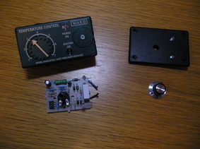
The original housing and the circuit board of the propagator are shown on the left. The cover of the new control box and the control knob are shown on the right. The hole for the temperature setting and the two neon lights have been drilled and the lenses for the neon lights have been glued in place.
The original control housing was glued to the base and had to be carefully cut away using a mini drill fitted with a cutting disc. This took a few minutes. Once the housing had been removed the circuit board and wiring was exposed. A multimeter was used to verify that the heating element was still operating by testing the continuity. The circuit was reverse engineered by identifying the components and following the PCB tracks. The circuit was then bench tested. The problem was identified as a broken mains input cable which had been pinched due to an excessive bend radius.
The original control housing was glued to the base and had to be carefully cut away using a mini drill fitted with a cutting disc. This took a few minutes. Once the housing had been removed the circuit board and wiring was exposed. A multimeter was used to verify that the heating element was still operating by testing the continuity. The circuit was reverse engineered by identifying the components and following the PCB tracks. The circuit was then bench tested. The problem was identified as a broken mains input cable which had been pinched due to an excessive bend radius.
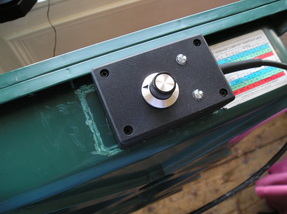
The completed unit with the cover and control knob installed. The two neon light lenses can also be seen on the right. One is permanently lit when the unit is connected to the mains. The other light comes on when the heater element is on and goes off when the set temperature has been reached. The labels for the control knob and neon lights have still to be added. A sleeved cable strain relief was also added. A small amount of silicone sealant was added around the exit of the strain relief unit to prevent water entering the control box.
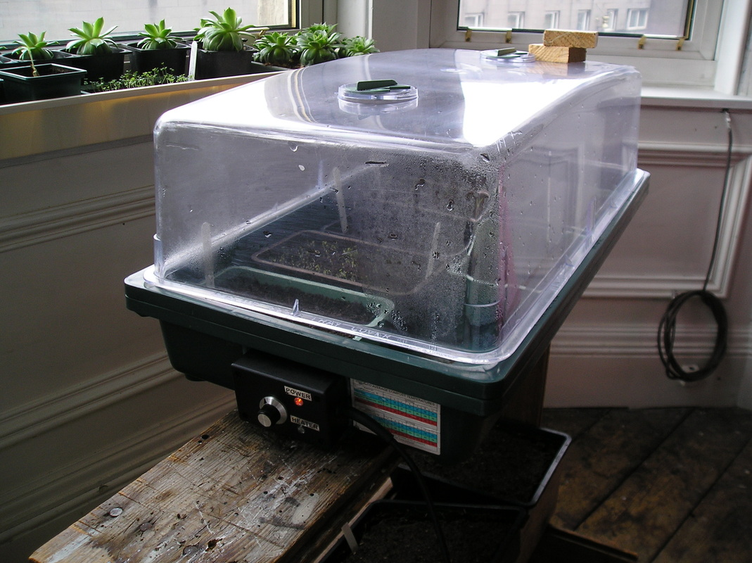
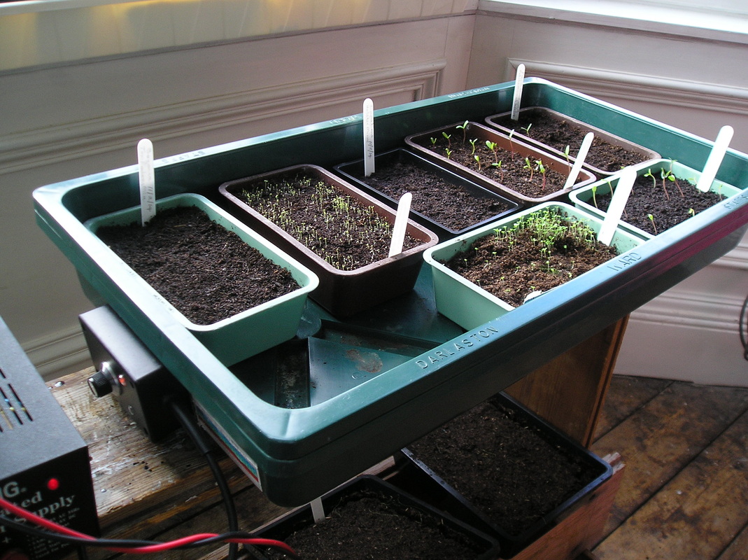
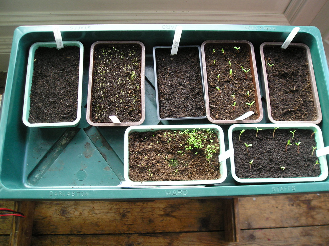
Below are a few pictures showing the repaired propagator in use in early 2014. The small germinating trays contain French Marigold, Alyssum, Begonia, Lobelia and Impatiens seeds. French Marigold seedlings germinated within a couple of days, Begonia and Impatiens took approximately 10-14 days before tiny seedlings could be seen.
|
|
|
