Background
I have had a small rechargeable torch for over 15 years which has been handy to have around the house. A couple of years ago it stopped working and i assumed that the rechargeable batteries were worn out so i would have to replace them. I put it aside and forgot about it and then the inevitable happened. I needed a torch and did not have one to hand. I immediately changed the nickel cadmium batteries and tested the unit. The bulb did not work so i assumed the bulb may also have blown. I opened the lens of the torch and checked the bulb. It was working correctly. I dismantled the lens unit of the torch further and found that one of the contacts connecting to the rear of the bulb had broken away. I had a couple of choices, throw the torch away and buy a new one or try to repair it. I reckoned it was worth a couple of hours to repair it and i also wanted to investigate the possibility of upgrading it by replacing the incandescent bulb with one or more LED's.
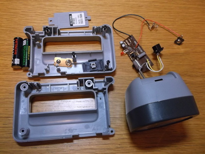
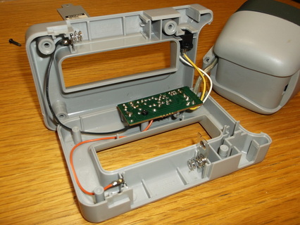
This picture shows the main torch components dismantled. The small PCB contains the circuitry that controls the charging of the batteries and the operating mode of the the torch, constantly on or flashing mode.
The batteries are 1.2V Nickel Cadmium (Ni-Cd) 500mAhr types.
The circuit diagram was produced from the control PCB by tracing the copper tracks, identifying the components and using the silk screen markings.
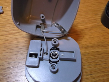
The head of the torch was opened and dismantled revealing the broken contact mounting. The metal strip was originally welded to the plastic panel holding the bulb making contact with the center contact of the bulb.
This had to be repaired before the torch would work again.
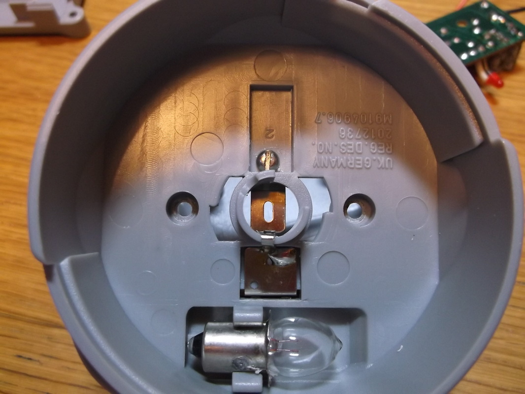
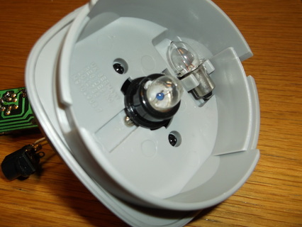
A hole was drilled where the original plastic weld held the metal contact strip in place. An M3 machine screw spring washer and nut were used to fix the contact strip in place. Here the slotted head of the bolt can be seen and the metal contact can be seen through the bulb mounting hole. A spare bulb can be seen in the lower part of the picture.
|
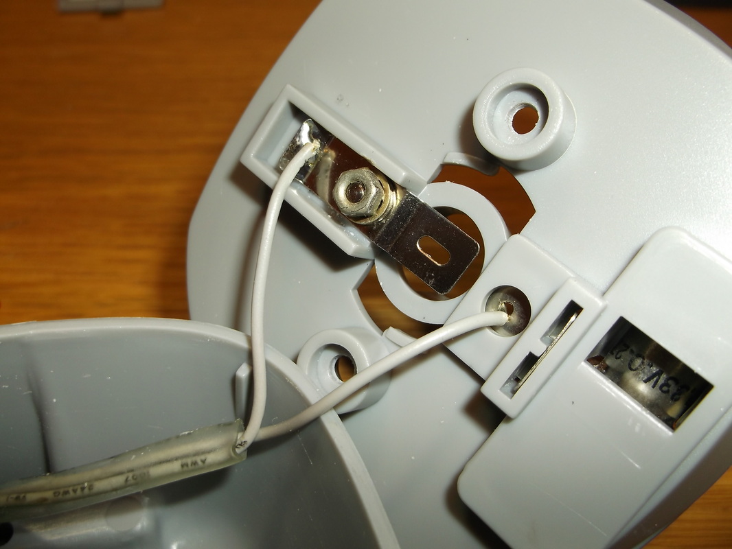
Here the rear of the torch head can be seen. The M3 nut and bolt can be seen holding the metal contact strip in place.
|
Here the torch head has been repaired and reassembled. The M3 machine screw slotted head can just be seen in the recessed area below the black bulb mounting.
Here the torch has been partially reassembled ready for testing.
The Ni-Cd batteries only provide 2.5V at best when fully charged and the bulbs are rated at 3V so the light output is not as high as it could be. As there is some space inside the body of the torch i plan to investigate adding a third battery and modify the PCB components as required to boost the light output.
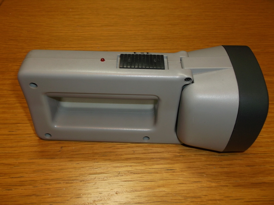
Here the torch has been fully re-assembled and new rechargeable batteries installed. Originally low cost 500mAhr batteries were installed. These were replaced by 2000mAhr batteries as they were already available.
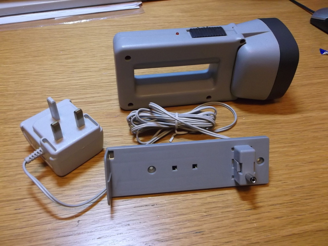
Here the torch, charging station and AC adapter are shown.
|
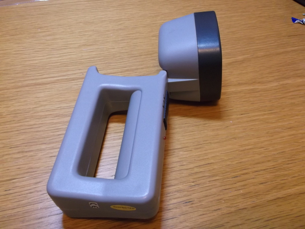
Here the rotating action of the torch head is demonstrated.
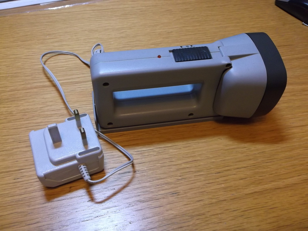
Here the torch mounted on the charging station is shown. The AC adapter output is 5.3V DC at 140mA unregulated.
|
Upgrade Plans
1. Add additional 1.2V Ni-Cd battery to increase output voltage from 2.4V(Nominal) to 3.6V(Nominal) to increase the light output of the incandescent bulb. The drive circuit and charge circuit will be analyzed and modified as required.
2. Replace incandescent bulb with one or more white LED's and any necessary drive circuitry.
