Background
After developing the prototype of LED driver circuit i decided to improve the performance and range of operation in a slightly modified version. The main design goals were still in place, small physical size , operation from battery with a wide supply variation.
After extensive testing of the LED Driver Circuit V1 there were a number of problems that i wanted to address:
To address these problems the following changes have been made to the circuit:
These changes have allowed the circuit to work more reliably over a wide power supply ranging from 2.5V to 6V with a much reduced variation in performance compared to V1 of the circuit.
After extensive testing of the LED Driver Circuit V1 there were a number of problems that i wanted to address:
- The reference voltage and hence the output current is derived from the power supply. As the battery voltage decreases the reference voltage and output current reduce.
- The upper switching point of the comparator is dependent on the power supply. As the battery voltage decreases this decreases also which in turn reduces the output current.
- The output transistor drive circuit is difficult to design to work reliably and efficiently over a wide power supply range.
To address these problems the following changes have been made to the circuit:
- The reference voltage is now derived from a 1N4148 low current diode.
- The upper switching point is now independent of the power supply voltage. Two 1N4148 low current diodes are used to generate this.
- The output transistor drive circuit is now driven by a current source rather than a voltage source.
These changes have allowed the circuit to work more reliably over a wide power supply ranging from 2.5V to 6V with a much reduced variation in performance compared to V1 of the circuit.
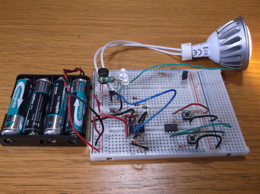 LED Driver Circuit V2 on breadboard driving a 5 Watt LED lamp.
Here V2 of the driver circuit has been constructed on plug in breadboard for testing.
There are some spare components( Microcontroller, switches and wires) to the right hand side of the breadboard that were left over from another project.
In this prototype two discrete white LED's can also be seen. These were added after the original circuit was designed and are intended to be used as 'side looking' LED's for bikelights.
These worked very well and removed the need for a separate drive circuit.
The circuit was tested using 2,3 and 4 rechargeable batteries giving a supply voltage of 2.5V, 3.75V and 5V. The 6V supply was generated using a 6V SLA.
The circuit was still giving a strong output with a battery voltage of 2.1V.
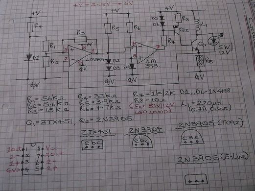 Circuit Diagram for LED Driver Circuit V2.
This is the circuit diagram for the circuit under test.
The original LM339 was replaced by a LM393 which is basically a dual version of the quad LM339 IC. Using the LM393 reduced the circuit space required.
The circuit can drive LED lamps varying from 0.5 Watts to 7 Watts with only the values of R8 and Rs having to be changed depending on the LED lamp power. If larger wattage lamps have to be driven then Q1, R8, Rs and L1 would have to be changed to handle the larger currents.
Photographs of circuit constructed on PCB to follow soon.....
