Background
Since developing the switch mode current driven driver circuit for the LED torch and bike lights i have had many requests to develop a similar low voltage drive method for the rectangular red rear bike light and the greenhouse grow light i had previously developed. These ran from 12V and 18V supplies respectively. Not everyone has access to surplus laptop PSU's and PC power supplies to provide these voltages and they are quite bulky if you only want to supply a small number of devices. The circuit developed here can be powered from a small battery pack between 4V and 6V such as 4xAA size batteries(Ni-Cd, Ni-MH or Alkaline) or from a 4.5V-6V DC mains adapter.
This project uses a Texas Instruments TI497A switch mode power supply control IC. This is a little unusual in that it achieves control of the output voltage by using a fixed pulse width and varying the frequency rather than the more conventional fixed frequency variable pulse width approach.
I plan to use this project as a stepping stone to the ultimate implementation of controlling the circuit with a low cost PIC processor such as a 12F675 which would be used to control the pulse stream to the power driver circuit and the inductor, diode, capacitor output circuit.
The Texas Instruments TL497A chips are not readily available on the usual hobby and commercial suppliers websites and where they are can be quite expensive for a low cost system that i want to develop.
I was able to obtain some surplus chips on EBay for a reasonable cost. I suspect they are quite old as they are marked as being made in England and have a marking of '531A' suggesting week 31 of either 1985 or 1995.
I spent a good few hours reading through the supporting documentation and specifications and calculating the components required.
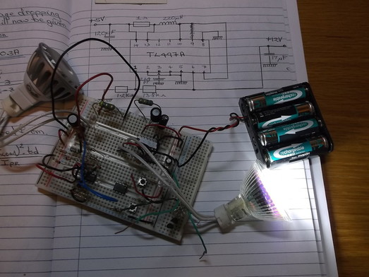
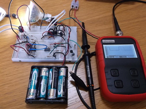
The circuit can be seen in this photograph together with a first prototype on the breadboard. The circuit is driving a 1.6W LED lamp i have previously used in torches and bike lights.
I was able to obtain some surplus chips on EBay for a reasonable cost. I suspect they are quite old as they are marked as being made in England and have a marking of '531A' suggesting week 31 of either 1985 or 1995.
I spent a good few hours reading through the supporting documentation and specifications and calculating the components required.
The circuit can be seen in this photograph together with a first prototype on the breadboard. The circuit is driving a 1.6W LED lamp i have previously used in torches and bike lights.
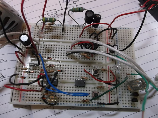
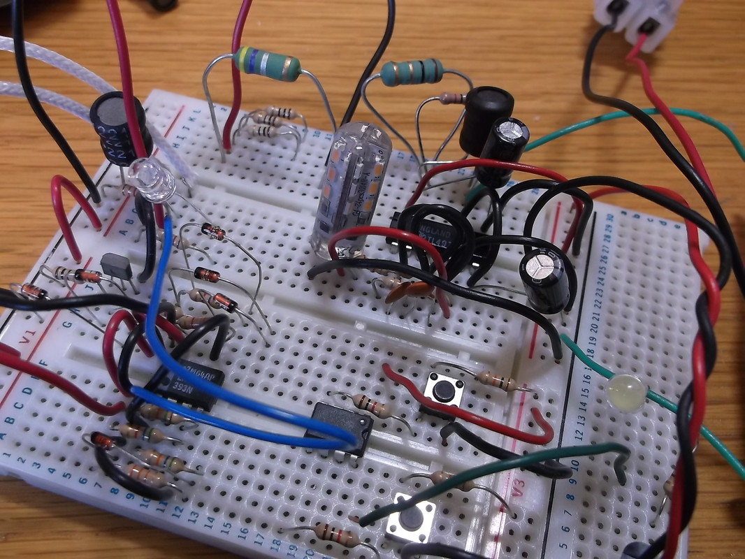
This is a close up of the first prototype using the TL497A driver chip.
On the same piece of breadboard to the left iis the original LM393 based switch mode driver i developed some time ago which has been used in many projects to date. At the bottom right is a PIC, 12F675 which will hopefully eventually replace much of the TL497A functionality.
Although the TL497A circuit looks quite complex on the breadboard it is a very simple circuit due to all the major control components being on the chip itself.
The chip is intended to supply relatively low power devices but its performance can be extended by adding external power transistors and diodes allowing higher power outputs to be achieved.
After the initial calculations were completed and the circuit constructed it was testing using various suitable loads that have previously been driven by a 12V battery or a switch mode current circuit.
In this picture the rectangular red bicycle light is being driven from 4 AA Ni-Cd batteries. The internal circuitry of the light was originally designed so that it would be driven from a 12V DC source.
The level of light output was indistinguishable from that obtained when the light was driven by a 12V battery.
The oscilloscope shows the wave form at the output of the TL497A drive transistor where it connects to the inductor. The trace was very steady as the load was fixed.
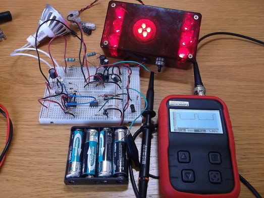
In this picture a 12V, 1.5W small LED bulb is being driven from the TL497A. Again the scope trace is very steady indicating good stable operation.
|
The brightness of the bulb in the previous picture makes it very difficult to see its outline so this picture shows it with the driver switched off.
|
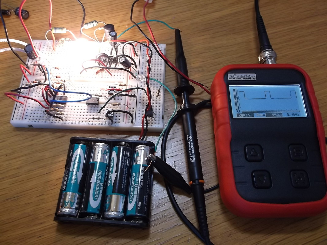
This picture shows the TL497A driving a 12V, 1.6W LED lamp. This load was pushing the drive circuit to the limit of its performance and the TL497A current limiting feature was being activated which shuts down the driver stage to protect it from damage. As a result the scope trace is much less clear as a result of the jitter of the signal.
Given that the circuit is operating right at and slightly beyond its maximum performance the light output was still very good and was no different to that obtained driving the LED lamp from a 12V DC source.
Now that the basic concept has been proved i intend to design and build TL497A based circuits that will drive the rectangular red LED bike light used here for testing and for the greenhouse red grow light which operates from 18V and above. The circuits will be retro-fitted to the current systems. In the case of the greenhouse grow lights it will mean that they can now be driven from a 5V-6V mains adapter freeing up some space as the laptop mains adapter can be removed.
