Background
I bought this variable, 3V-12V 1.2A output voltage power supply from Tandy (UK brand name for Radio Shack) during their closing down sale around 1999. It served very well in various test projects over the years and until it failed in September 2015 while powering my Internet Router it had been totally reliable.
It failed quite unexpectedly and i suspected that it would be due to a component failure however when i opened up the case i found that one of the plastic control knobs that selected the output voltage polarity had perished and snapped, i suspect due to the heat generated by the internal components.
The circuit board showed signs of heating around a resistor which was directly under the plastic knob so as well as repairing the plastic knob i decided to replace the heat damaged resistor.
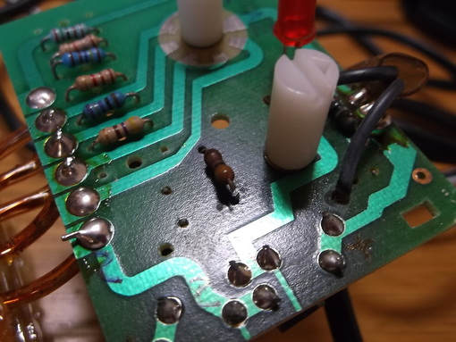
This shows the underside of the circuit board. The output voltage polarity selector switch has been removed and repaired using super glue then allowed to dry for several days.
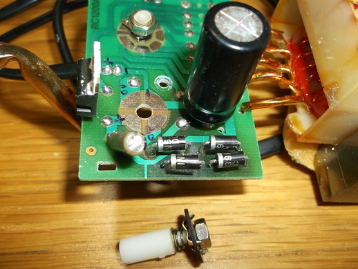
The heat sink has been removed to make access to the components easier. While doing this i noticed that the mounting of the LM317 and the heat sink was a little unconventional and that the thermal transfer grease had some what dried out so it was renewed.
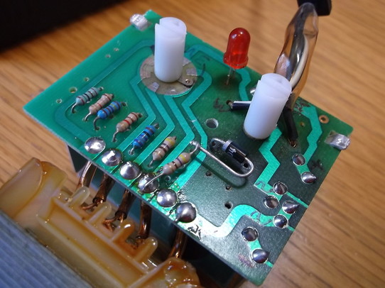
This shows the circuit board with the repaired selector switch re-installed. The heat damaged resistor can be seen just to the right of the switch. The heat damaged resistor limits the current through the red LED. The string of other resistors are used to generate the output voltage of the LM317.
The heat damaged resistor was sufficiently discoloured to make it impossible to identify it's value so one leg was cut and a multi meter was used to measure it's value as approximately 440 Ohms.
This shows a close up of the heat damaged resistor with one lead cut from the circuit board.
There is some cosmetic damage to the circuit board surface but the structure is unaffected.
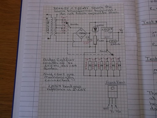
The PCB tracks were traced to create a circuit diagram.
The circuit is based around the LM317 adjustable voltage regulator. To set the output voltage only two resistors are required. The mains transformer has a number of tappings.
The rotary switch operates on the transformer tappings and the resistor network around the LM317. When the rotary selector switch is moved the appropriate mains input voltage is selected and the corresponding resistor is selected to set the output voltage.
This arrangement ensures that the power dissipation in the LM317 is kept to a minimum. If the transformer had only one output voltage then the LM317 would have to dissipate a very large amount of power especially at the lower output voltages.
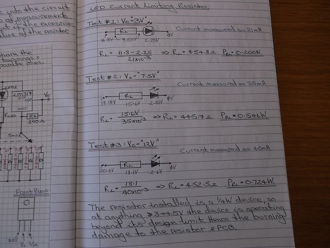
The LED current limiting resistor was badly damaged due to overheating. The calculations in the above photograph show that the resistor dissipates between 200mW and 724mW depending on the input voltage. The resistor is rated at 0.25W. This is because the the LED is powered from the output of the bridge rectifier. As a result the voltage across the LED and resistor can vary between 12V(rms) and 21V(rms). The calculations show that the current trough the LED varies between 21mA and 40mA.
|
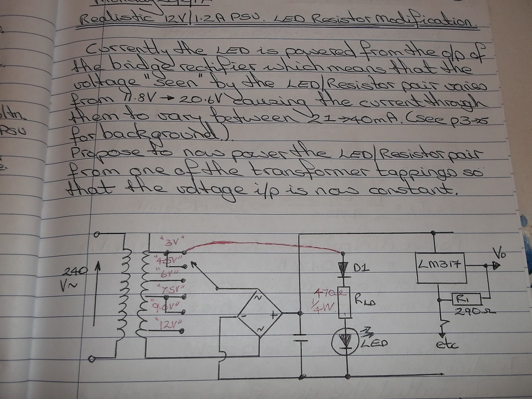
This photograph shows the circuit diagram of the modification made to the PSU to minimise the power dissipation in the series resistor. The LED is now powered from the "3V-4.5V" outputs of the AC transformer. This produces 12V(rms). The components were wired on the surface of the PCB. A 1N4001 diode was added into the circuit to protect the LED from reverse voltages. This circuit limits the LED current to 20mA(approx) for all voltage inputs and the power dissipation in the resistor is limited to 176mW.
|
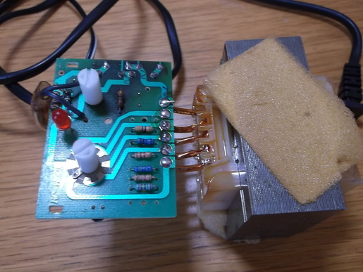
This picture shows the new resistor and diode added to the circuit to limit the current to the LED for different input voltages.
The resistor is connected to the lowest AC output of the transformer.
It is not good practice to have components mounted like this however in this case the components are not in close proximity to other ones. The component leads actually form quite a stiff structure and any vibration will not cause them to move.
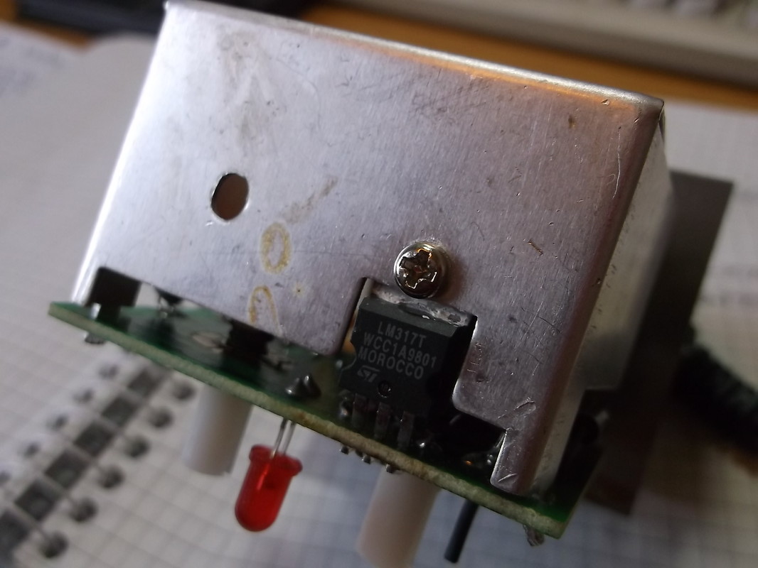
This picture shows the heat sink mounting arrangement of the LM317 adjustable voltage regulator. This is an unusual method of attaching the heat sink and is likely to result in a poor contact between the metal tab of the device and the heat sink. It was decided to improve the mounting of the LM317 by using a more conventional method.
|
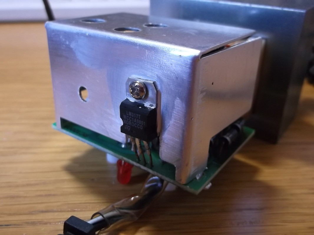
The heat sink was removed from the PCB and the LM317 was desoldered. A new mounting hole was drilled in the heat sink to allow the full body of the LM317 to be attached to it. The LM317 was mounted on the heat sink and the heat sink attached to the PCB. As the LM317 leads were now too short to reach the PCB short lengths of cut off component leads were used to extend the leads to the PCB. A new layer of heat transfer grease was used to mount the LM317 on the heat sink
|
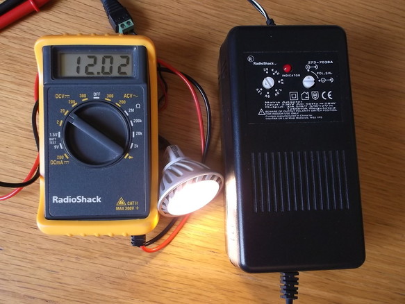 12V 1.2A PSU being tested using a 12V, 5W LED lamps as a test load.
The PSU was re-assembled in the case and tested with a 12V 5W LED lamp used as the test load.
The Power supply operated as expected and the case temperature was much lower than it previously had been before it failed.
The output voltage was monitored during the test and remained steady at 12.02V over the two hours of the test.
This PSU was being used to power an Internet router when it failed. I have since moved to a system where all routers, modems, external disk drives are powered from a converted PC PSU so this unit will be put into storage as a spare or for electronic projects.
