Background
My mother purchased a reversing camera for my dad as a christmas present a few years ago. I had put off installing it as it would mean drilling a hole in the body work however after the 3 year warranty had expired i decided to press ahead and install it.
The reversing camera consists of a camera unit that is mounted at the rear of the car and needs to be connected to the reversing light wiring. The camera has a 2.4GHz transmitter built in which transmits to the display unit so no cables need to be lead from the rear to the front of the car. A colour display unit is mounted at the front of the car which only needs to be connected to the accessory socket to provide power to it.
The reversing camera consists of a camera unit that is mounted at the rear of the car and needs to be connected to the reversing light wiring. The camera has a 2.4GHz transmitter built in which transmits to the display unit so no cables need to be lead from the rear to the front of the car. A colour display unit is mounted at the front of the car which only needs to be connected to the accessory socket to provide power to it.
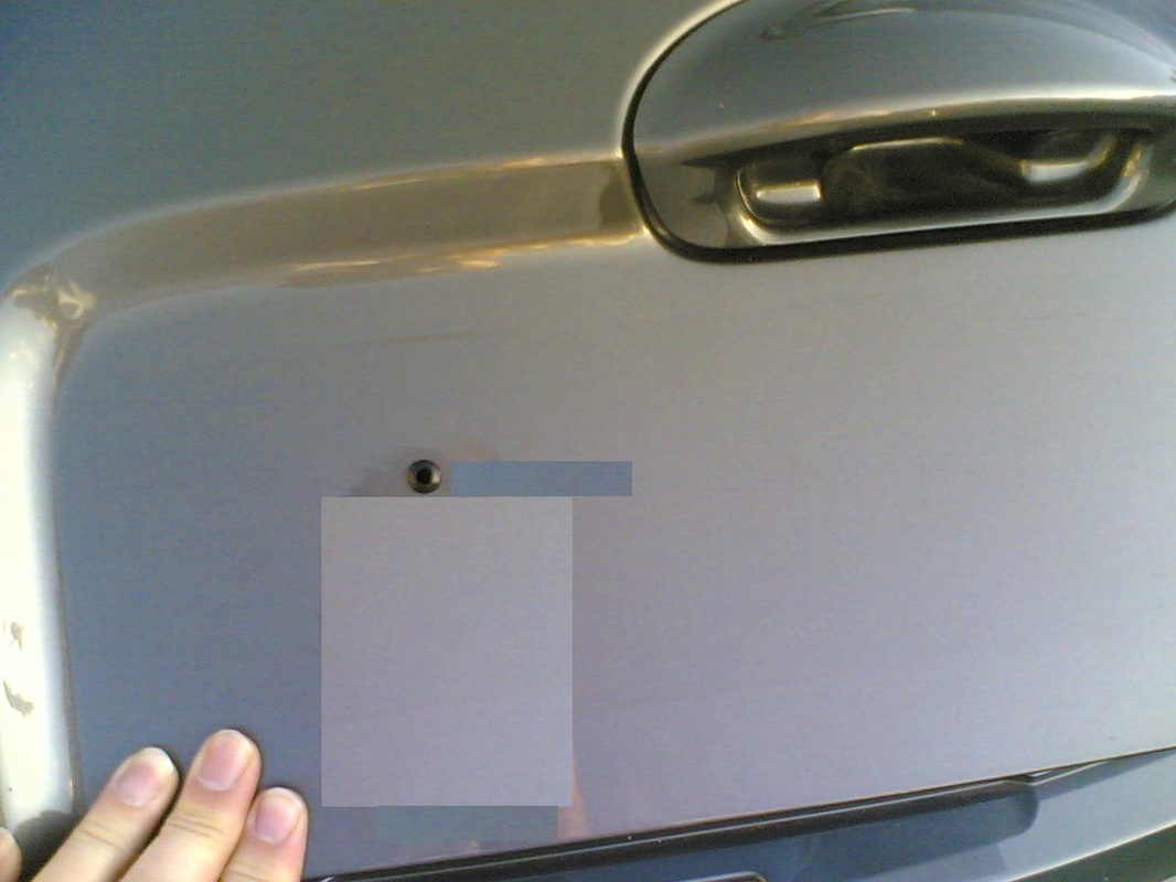
The camera is intended to be mounted on the number plate. The number plate was removed and a hole was drilled to take the wiring for the camera. A rubber grommet was fitted to the hole to avoid chafing of the wires on the rough edges, minimise water ingress and prevent corrosion of the exposed metal.
When the wires had been fed down through the rear quarter panel they were connected to the reversing lamp wires using insulation displacement automotive connectors. Fortunately there was easy access to the rear light cluster and its wiring. I had a workshop manual for the car however the electrical circuit diagram was corrupted and the labelling was difficult to follow. Fortunately i contacted the publisher and they were able to email a corrected version of the circuit diagram.
Then my mother replaces her car.........
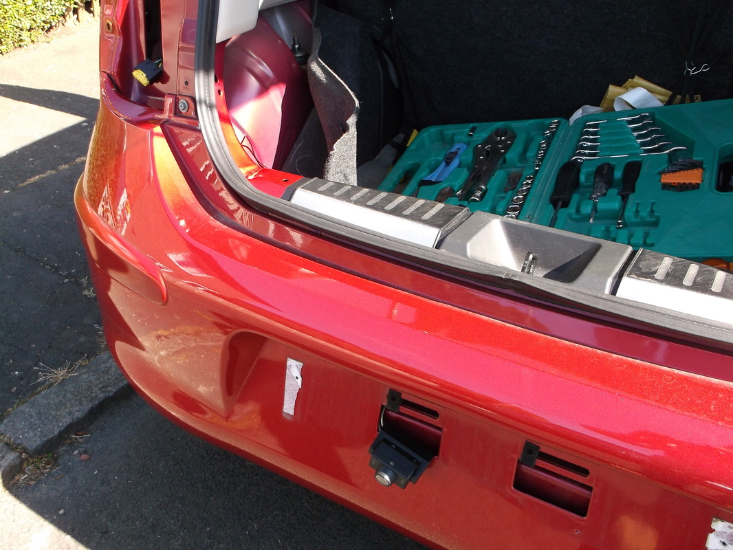
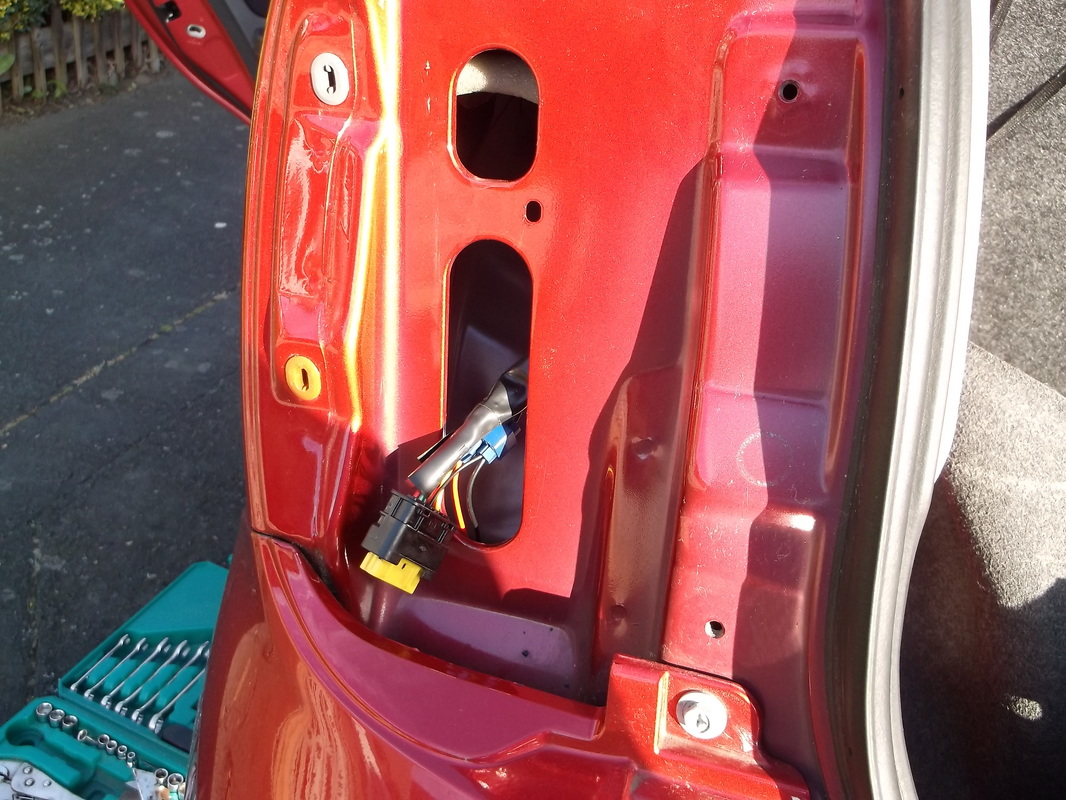
When my mother decided to replace her car she was keen to still have a reversing camera. As an option on the new car it would cost over GBP400 so i decided to transfer the camera to her new car. Due to the location of the number plate light the camera had to be mounted on the bottom edge of the number plate rather than the top. The number plate was removed to thankfully reveal access holes through the bumpe and into the chassis of the car thus no drilling was required. 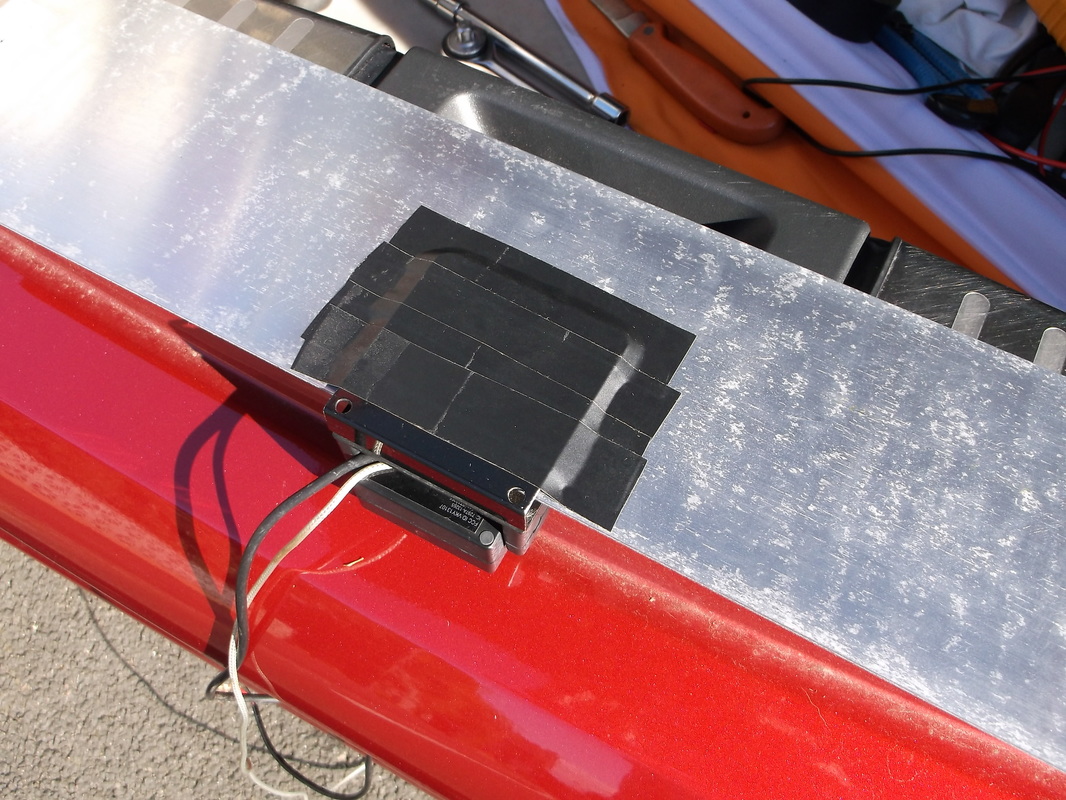
The camera was secured to the back of the number plate using double sided sticky pads. Electrical insulating tape was then applied over the back of the mounting plate to try to provide as much water proofing as possible.
|
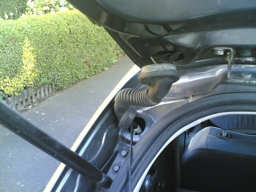
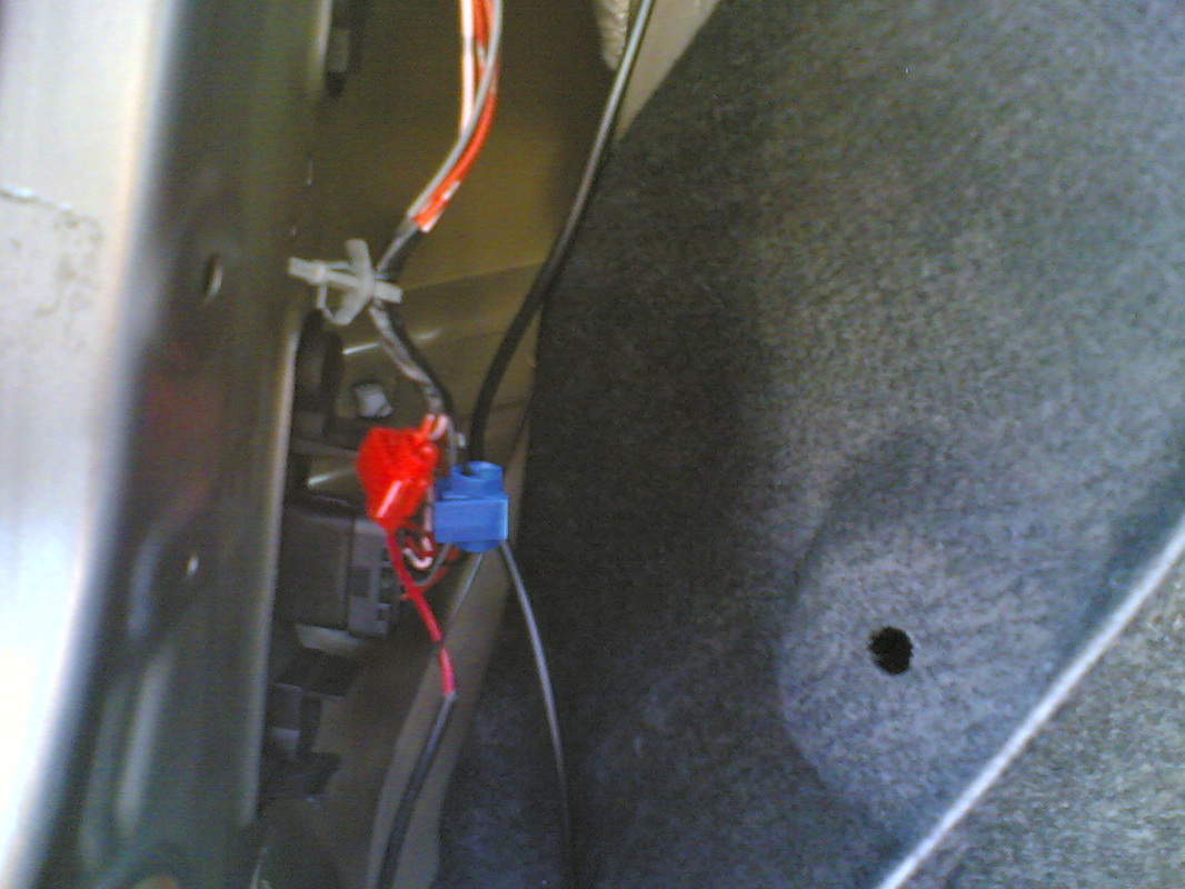
The wire was fed through the hole drilled behind the number plate and with the internal panel of the rear door removed it was fed up the frame of the door and out the rubber connector as shown in this photograph. The power wires were extended using automotive grade wiring. The wires were fed through the rubber connector and down into the rear quarter panel of the car.
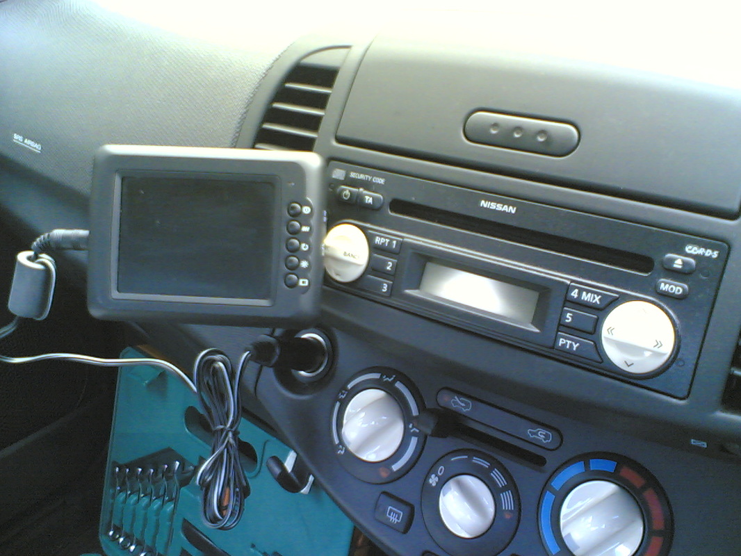
The display unit was supplied with a number of mounting options, dashboard, windscreen and ventilation vent. I chose the ventilation vent option as shown in this photograph. After all the connections were checked the system was tested and then all the panels were put back in place.
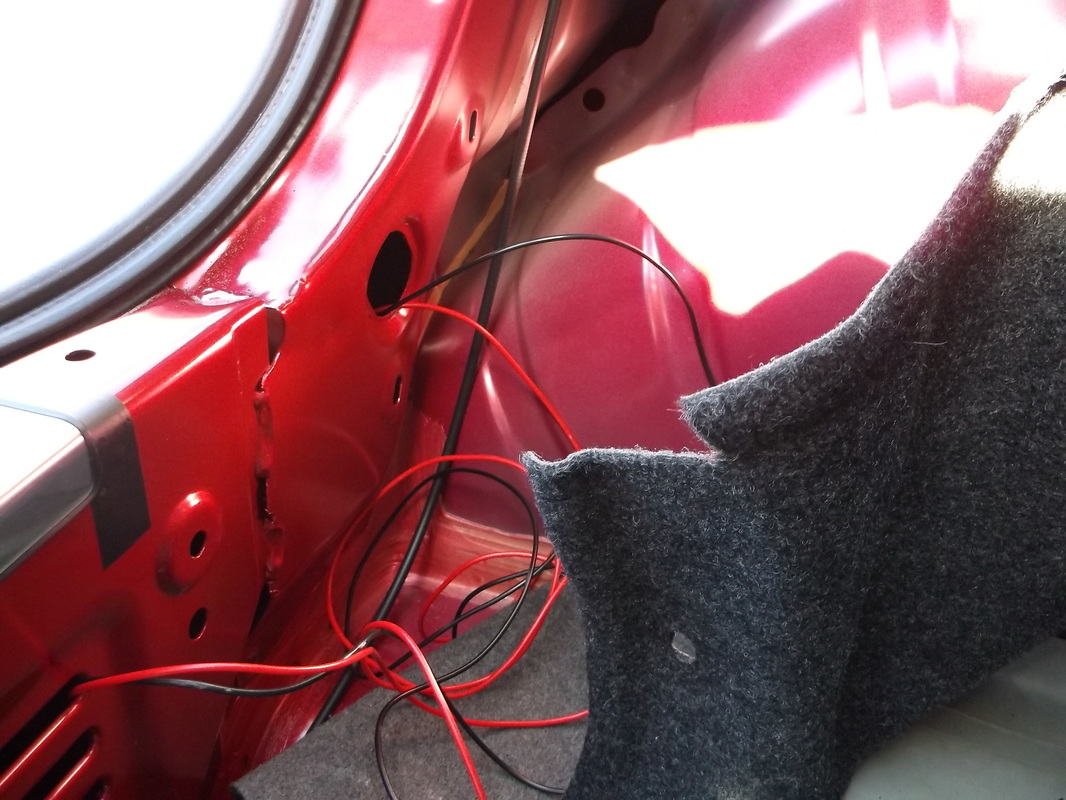
After a bit of fiddling i was able to thread the cables through the chassis channel and into the boot of the car. The boot lining had to be removed to reveal the holes but it is easily secured back in place. The thick black cable running through the wiring is actually the remote fuel cover release cable.
Unfortunately there was no workshop manual with a circuit diagram available and it was impossible to get access to the wiring of the rear lamp cluster from the boot to identify which cables connected to the reversing light so i had to remove the rear light cluster to get access to the connector and wiring and use a multimeter to identify which connections became live when the gearstick was put into reverse. Fortunately the rear light cluster was easy to remove as there were no hidden bolts.
|
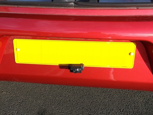
This picture shows the camera mounted on the lower edge of the number plate. As the camera had to be mounted on the lower edge of the number plate to avoid blocking the number plate light, black tape had to be used to cover the light sensor which switches on the infra-red diodes so that the camera would work at night otherwise the number plate light would shine directly on the sensor tricking the camera into thinking it was daylight although the surrounding area was dark.
This time the display unit was mounted on the windscreen using a suction mount as the vents were not suitable.
