Background
For some time i have been developing modular lighting systems for greenhouse, propagator, path and bike lighting using 12V LED bulbs which have greatly reduced in cost over the past 3-4 years(time of writing is 2016). I have also recently designed an easily configurable circuit which can be used to drive a 12V LED bulb from a 5V or 6V source. Click here for further details. I decided to build a simple prototype handheld torch using the driver circuit and the plastic plumbing parts to show how easy it is to use this modular concept to build lighting systems from readily available parts.
The prototype shown here is larger than actually required to house the components. I used what parts i had available to prove the concept. In the final version the size may well be smaller although the current size does provide good a good balance and feel in the hand. The light output of the LED can be changed by installing a different wattage bulb and changing the current sense resistor on the driver circuit board.
The prototype shown here is larger than actually required to house the components. I used what parts i had available to prove the concept. In the final version the size may well be smaller although the current size does provide good a good balance and feel in the hand. The light output of the LED can be changed by installing a different wattage bulb and changing the current sense resistor on the driver circuit board.
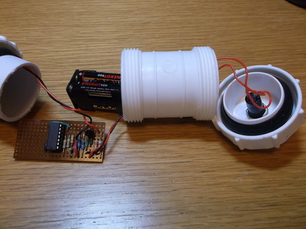 Components of rear half of torch.
This picture shows the rear half of the torch. The on/off switch is mounted on the rear of the torch.
The battery pack is mounted in the rear section. In this version the power is supplied by 4 x 1.2V Ni-MH rechargeable batteries.
The LED driver circuit is mounted in the middle section of the torch.
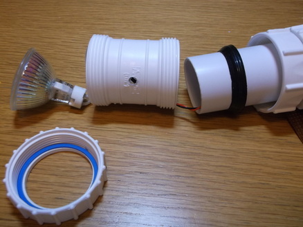 Components for front half of torch.
This picture shows the front and middle sections of the torch.
The middle section houses the LED driver printed circuit board.
The front section houses the LED bulb and the bulb holder.
The black rubber seals hold the various sections together.
The holes in the front section have no function in this application. They are present simply because i had used these parts in a previous prototyping project. In a final version there would be no holes.
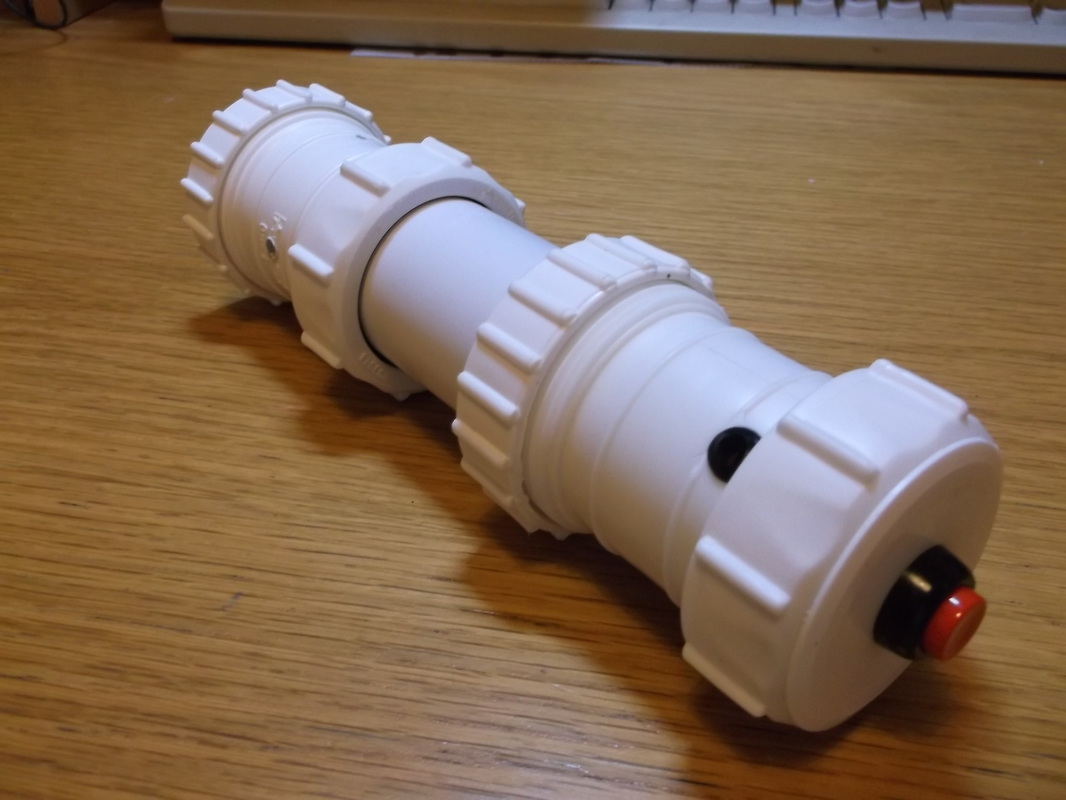
Rear of assembled torch.
This picture shows the assembled prototype torch viewed from the rear. The red button is the on/off switch. The black dot is in fact a rubber grommet. This part of the torch was used in another prototype project.
|
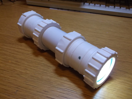
Front of the assembled torch.
This picture shows the assembled prototype torch viewed from the from with the torch switched on. In this case a 1.6W LED bulb is installed. This particular bulb has a glass cover enclosing the the individual LED's.
|
Adjustable Torch
When i first designed the modular torch i always intended that it should be adjustable so that the light output could be directed at a specific work area. The fixed front section was removed and replaced by an adjustable section. This allows the light output to be directed at any angle between zero and 90 degrees.
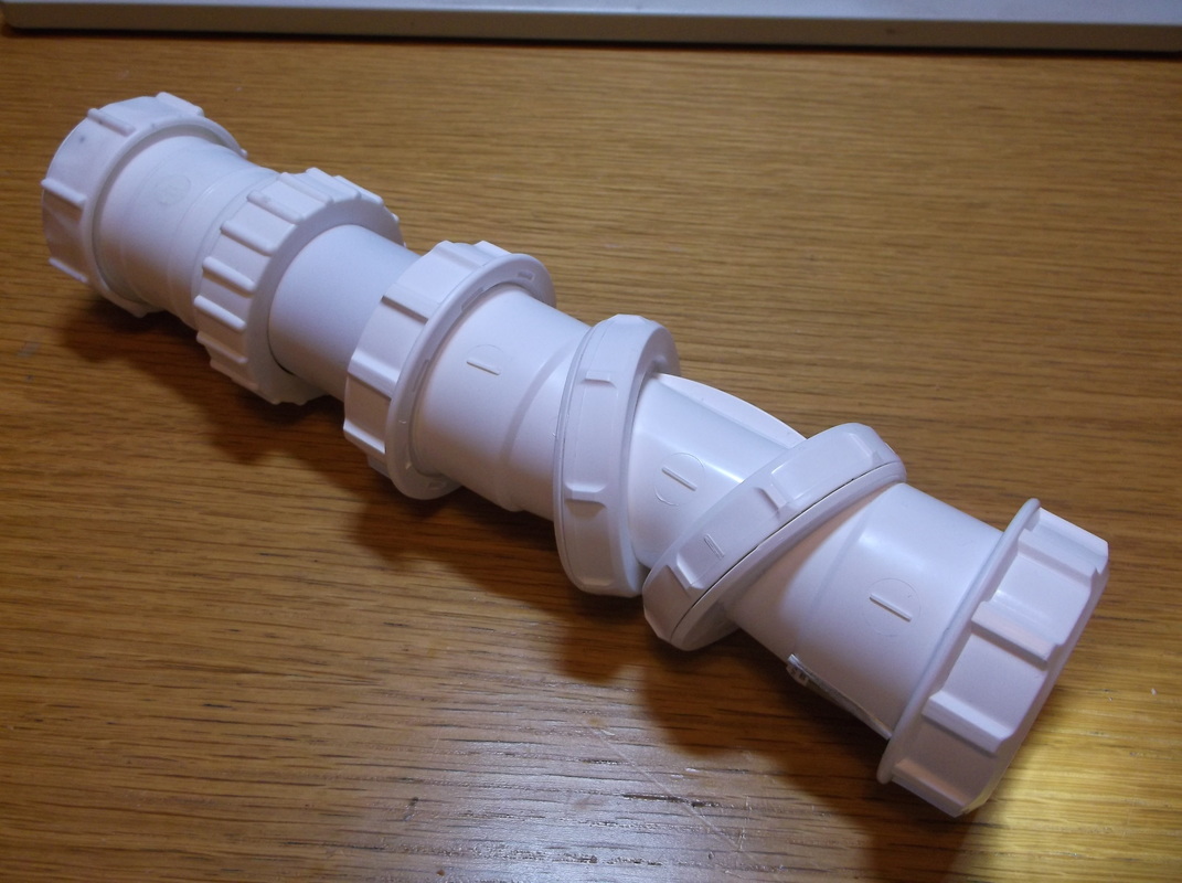
Adjustable torch, straight ahead.
Here the adjustable front section has been installed.
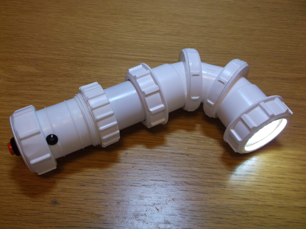
Adjustable torch, set to 90 degrees.
In this picture the light output has been set to 90 degrees.
|
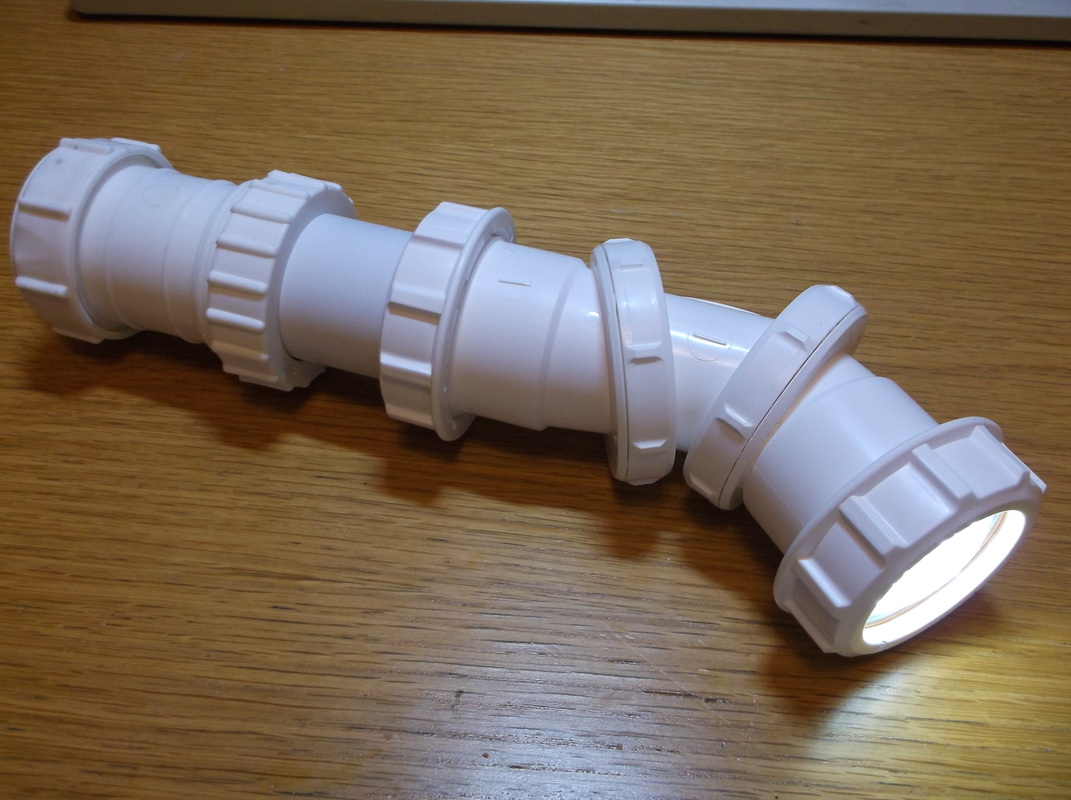
Adjustable torch, set to 45 degrees.
In this picture the light output has been set to 45 degrees.
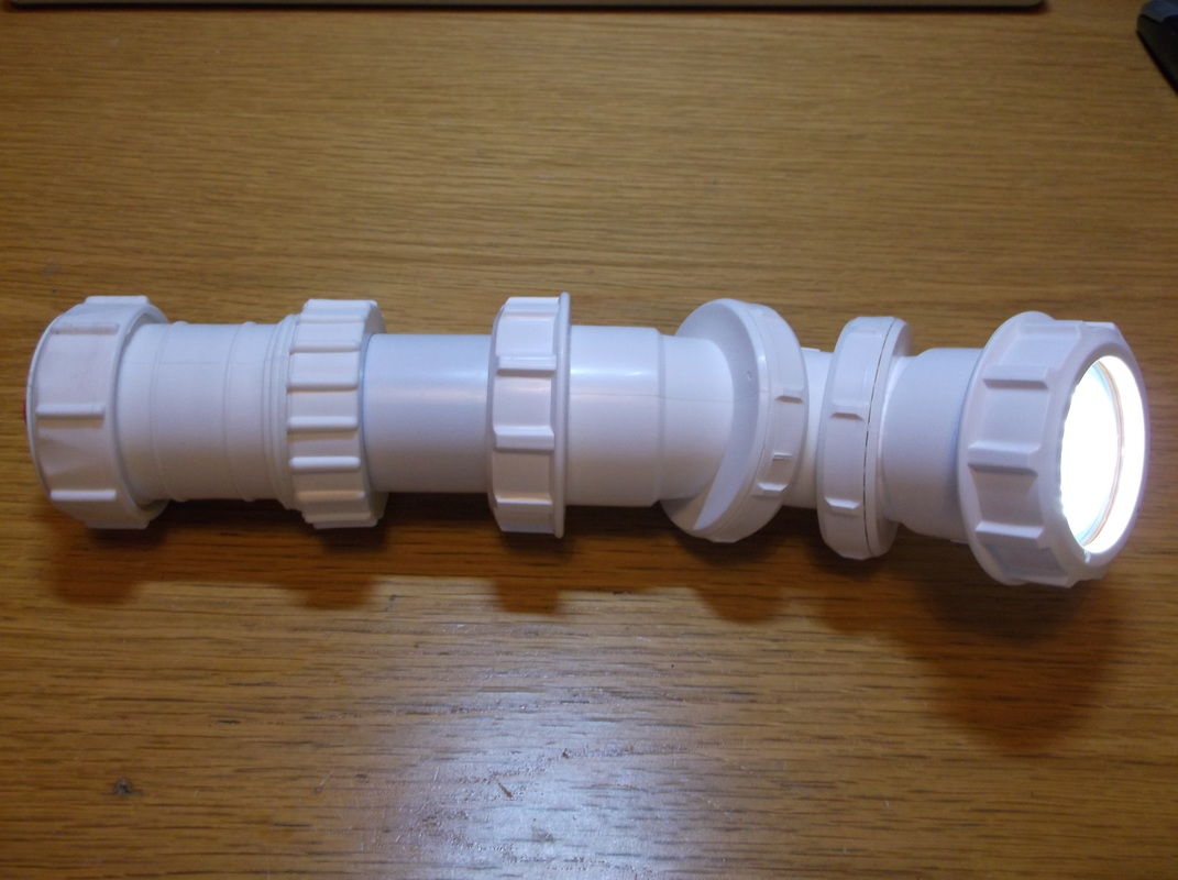
Adjustable torch set to an angle and pointed upwards to direct light at a specific area.
In this picture the light output has been set to approximately 30 degrees and and angled upwards to illuminate a specific work area.
|
