Background
For some time i had in mind developing a microprocessor controller power supply. By microprocessor controller i mean the processor is at the heart of the power supply control system not acting as a supervisory element. While developing the switch mode LED driver circuits i could see that there was a good possibility that this could be achieved using Microchip PIC CPU's such as the 12F675 which i have used in a number of other projects. These are 8 bit devices that come in a compact 8 pin DIL package. They have digital and analog input and output pins, on board timers, analogue to digital converter and comparator modules.
The objective of developing this project was to replace the TL497A circuit which was used in other prototype projects. The TL497A is a very versatile component but will only operate down to 4.5V whereas i would like to be able to operate down to 3.0V-3.5V. Parts of the TL497A chip will work as low as 3V and Texas Instruments suggest a circuit to 'bootstrap' the chip and operate it from it's own output voltage! However that requires more components than i want to use where space is very limited so i decided to go ahead with developing the PIC 12F675 based project.
The objective of developing this project was to replace the TL497A circuit which was used in other prototype projects. The TL497A is a very versatile component but will only operate down to 4.5V whereas i would like to be able to operate down to 3.0V-3.5V. Parts of the TL497A chip will work as low as 3V and Texas Instruments suggest a circuit to 'bootstrap' the chip and operate it from it's own output voltage! However that requires more components than i want to use where space is very limited so i decided to go ahead with developing the PIC 12F675 based project.
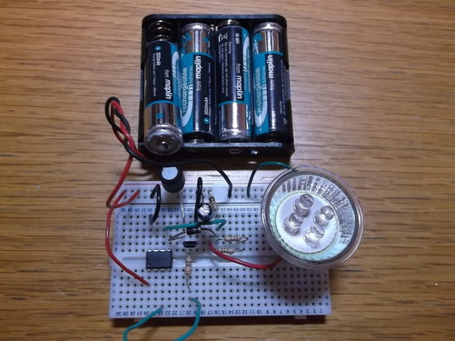
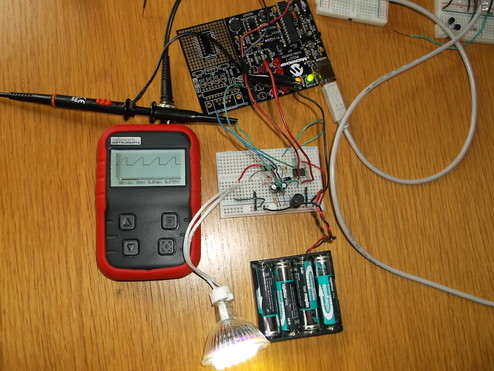
This is the basic circuit constructed on breadboard. The PIC 12F675 has been pre-programmed with the control software. For clarity the PICKit1 programmer has been removed so that the simplicity of the circuit can be seen. The circuit consists of just 8 components.
The circuit is being driven by 4x 1.2V Ni-MH batteries. The load is a 12V 0.4W LED lamp.
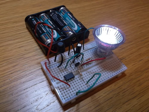
This picture gives a better view of the components on the breadboard while it is driving the 12V, 0.4W LED lamp.
The LED light output is too high to look into with the naked eye and has been photographed at an angle as the camera iris closes up if it is pointed directly at the LED.
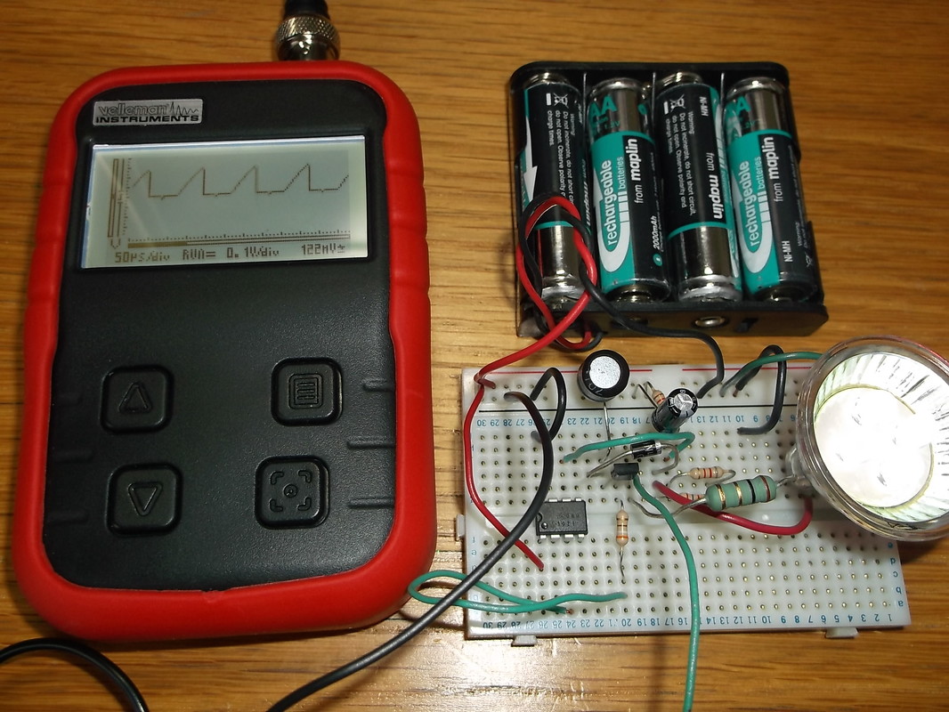
Inductor current waveform measured over sense resistor.
In this picture a 1 ohm resistor has been inserted into the emitter of the transistor to sense the current flowing when the drive transistor is switched on and 'charges' the inductor. The oscilloscope shows the inductor current ramping up linearly to a peak of approximately 300mA.
|

Drive transistor collector voltage waveform.
In this picture the oscilloscope shows the collector voltage of the drive transistor. The low periods of the waveform indicate when the drive transistor was switched on and the current in the inductor was ramping up.
|
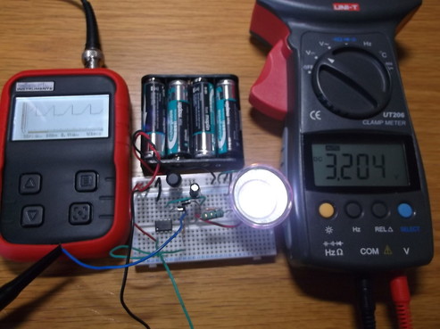 Inductor waveform, battery drive voltage and light output from 0.4W LED lamp.
This picture shows the circuit operating from a battery voltage of just over 3.2V and producing an excellent light output.
The oscilloscope shows the voltage across the current sense resistor in the emitter circuit of the drive transistor.
This shows that the circuit will operate very well when operating from a battery pack that is close to exhaustion.
 The 12F675 connected to PICKit1 to reprogram it to drive a 1.5W LED driver.
This picture shows the prototype circuit connected to the PICKit1 programmer.
The PIC 12F675 has been reprogrammed to drive a 12V 1.5W LED lamp. A second electrolytic capacitor was added to the output circuit to provide the calculated value.
The oscilloscope shows the voltage across the current sense resistor in the drive transistor emitter circuit.
The modifications to the circuit including the component calculations and re-programming the 12F675 took just a few minutes showing how flexible an approach this circuit could provide to generating higher voltages from low voltage battery packs.
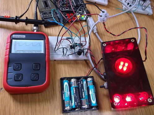 The 12F675 connected to PICKit1 to reprogram it to drive a rear bike LED light consisting of .4W LED lamp and two strings of 5 x LED's.
This picture shows the PIC PSU driving the red LED rear bike light i developed a few years ago which up until now was driven from a 12V sealed lead acid battery.
The light output was compared being driven from a 12V supply and from the PIC PSU powered from 4 x AA Ni-MH batteries. There was no noticeable difference.
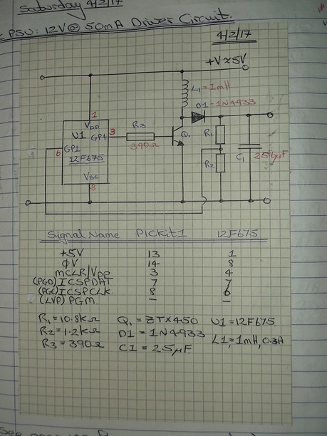 PIC PSU (12F675) Circuit Diagram with component values.
This is the very simple circuit diagram used in this prototype project.
The micro-controller is a Microchip 12F675. The drive transistor is a ZTX450 NPN silicon type and the inductor is a 1mH radial type device capable of a steady state DC current of 300mA. The flyback diode(D1) is a fast reverse recovery type 1N4933.
Resistors R1 and R2 provide the output voltage sample which is fed back to one of the comparator inputs of the 12F675. The control program of the 12F675 uses the output of its internal comparator to drive the transistor Q1.
Together, these components and the control program running in the 12F675 provide a voltage output of 12V from an input of 3.5Vto 5.5V.
