Background
My neighbour has a cordless grass strimmer powered from a pack of 15 x NiCd(1.2V) batteries. The strimmer and battery are now about 8 years old(as of August 2017) and although the strimmer is in very good condition the battery has been showing signs of age and required a few repairs a couple of years ago.(Click here for more information). Recently the strimmer started to operate intermittently. On opening the battery it was found that one of the metal connections between the batteries had corroded and was broken. Only the physical pressure of the batteries packed in the case kept the batteries in contact. Physical movement caused the contact to move and interrupt the electrical contact, hence the intermittent operation.
When i last repaired this battery pack i had considered converting it to mains operation but had put it off due to lack of time. After finding that there were no spare battery packs available and the cost of purchasing replacement cells and building them into a replacement battery pack would be much too expensive i thought this would make an interesting little project if surplus, spare parts could be used. Of course the easiest thing would be to purchase a new strimmer and send the old one for recycling but that would mean that lots of perfectly good components that had seen little use would be melted down or sent to landfill and there would be no opportunity to learn anything or put past experience to good use.
When i last repaired this battery pack i had considered converting it to mains operation but had put it off due to lack of time. After finding that there were no spare battery packs available and the cost of purchasing replacement cells and building them into a replacement battery pack would be much too expensive i thought this would make an interesting little project if surplus, spare parts could be used. Of course the easiest thing would be to purchase a new strimmer and send the old one for recycling but that would mean that lots of perfectly good components that had seen little use would be melted down or sent to landfill and there would be no opportunity to learn anything or put past experience to good use.
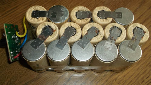
This picture shows the current state of the battery pack. The connecting strap between two cells at the bottom left of the picture has completely corroded due to the damp storage conditions and the leaking electrolyte from the batteries soaking into the cardboard covering.
The charging technique and the charger supplied have damaged the batteries over the years due to overcharging. There is no charge limiting circuitry to protect the batteries. It is up to the user to limit the charging time to 5 hours. The electrolyte has leaked from the batteries, soaked into the cardboard and has caused the connecting straps between the batteries to corrode where it is in contact with the cardboard.

This picture shows the 'head' of the strimmer unit.
The electric motor is housed in this unit. The strimmer has an adjustable length stem, a foot pedal(as shown in the picture) that allows the head of the unit to be adjusted for different terrain and a handle at the top of the stem that adjusts for comfortable handling of the strimmer.
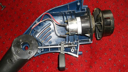
In this picture the head unit has been opened to reveal the DC motor that directly drives the strimmer head. The line feed and spool had been removed when the picture was taken.
The motor connecting wires have been removed to allow the motor DC resistance to be measured approximately. Using a multimeter this was measured as 1 Ohm.
The foot pedal mechanism that controls the angle of the head can also be seen.
p
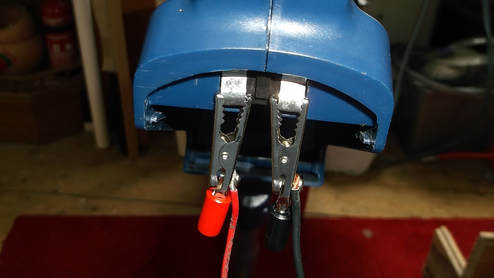
The strimmer was tested connected first to a 18.5V/65W and then a 18.5V/90W former laptop PSU.
The 60W unit went into power/over current protection mode and shut down immediately the strimmer was started causing just a slight pulse in the strimmer rotor.
The 90W unit powered the strimmer up to full speed within a few seconds giving very similar performance to that obtained with the fully charged battery pack.
This picture shows the PSU connected to the strimmer contacts that connect to the battery pack contacts using crocodile clips.
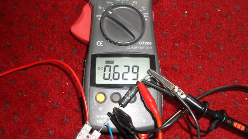
To get an idea of what current was drawn by the motor while running with the strimmer head attached, a 0.1 Ohm, 5W, 1% resistor was connected into the negative power connection.
The strimmer was powered from an 18.5V DC power supply, the one that will eventually be used to run the strimmer. The voltage was measured to ensure the output was not being pulled down by the current being drawn.
The current was measured as approximately 6.25-6.50A. When the strimmer is under load cutting grass it will most certainly be higher. The circuit proposed to drive the motor will help to prevent these large pulses experienced under load.
The photograph shows the meter reading the voltage across the current sensing resistor.
Circuit Analysis & Calculations.
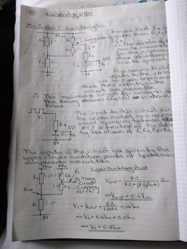
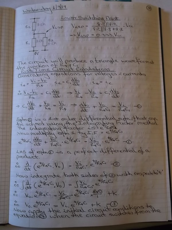
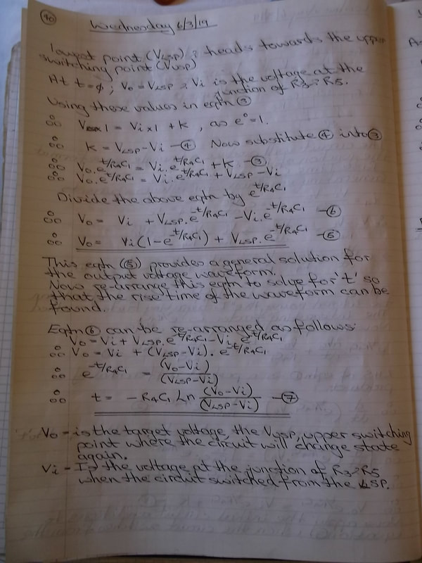
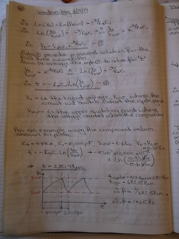
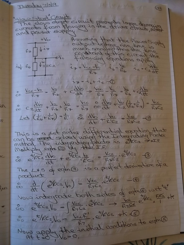
Below is a gallery of photographs of the calculations used to design and analyse this drive circuit. The mathematics involves First Order Differential Equations which are solved using the 'Integrating Factor ' method. The process used to analyse and solve the equations has been described but some basic level of electronic and mathematics knowledge is required.
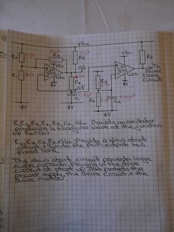
The objective of the drive circuit is :
1. Efficiently drive the electric motor in the strimmer from a DC power supply.
2. To minimise the start up currents by use of a soft start circuit to avoid damage to the drive circuit, motor and power supply.
3. To minimise the component count and circuit size to allow it to be mounted in the strimmer head beside the motor.
The circuit uses an LM393 high speed comparator to provide an oscillator and comparison module which generates a PWM output which in turn drives a MOSFET driver stage. The drive frequency is set at approximately 1500Hz.
Click on any of the photographs to view a larger image and to scroll through the other images. The photographs are in the correct order for the calculations to be followed.


More information on this project will follow soon.....
