Background : Single Front Bike Light (0.6W)
This was the very first LED bike light a made in late 2009. I used a 4 x white LED MR11 lamp as this was the first affordable LED lamp i came across. The first time i took it out on my bike it was impressive the light output it produced compared to a comparable incandescent bulb of the same wattage. This LED lamp has a stated output of 0.6 Watt. I originally used this as a front light but approximately 6 months later the larger 1.2 Watt MR16 LED lamp dropped to the same price so ii converted the original light to a rear light by adding a red filter and used the newer more powerful light at the front.
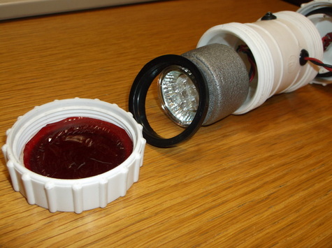
This picture shows the front of the bike light. As the LED lamp has no lense cover one was made from a piece of stiff plastic salvaged from an empty washing up bottle! Also shown is the red lense filter used to convert the light from use at the front to the rear. This is easily removed. It was originally a sweet wrapper!
The black rubber seal is belongs to the original plumbing part and serves two functions here, keep out water and help hold the LED lamp in place.
The silver foam is water pipe insulation which had a conical shape carved into the front to mount the LED lamp.
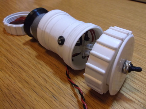
This picture shows the rear of the light. The body of the light has 'side looking' LED's which help the cyclist to be visible at junctions.
The 'side looking' LED's are mounted in LED holders to securely hold them in place. See below for further details.
The on/off switch is mounted at the rear and a rubber water proof cover is included.
The terminal block which connects all the wires together can be seen inside the main body.
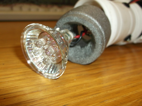
The early LED bulbs show their ancestry in that they still used silvered glass housings to handle the heat generated by the halogen/incandescent bulbs.
Although this was not necessary for the LED lamps, particularly as this one has only 4 x LED's they did provide a good beam pattern making the best use of the available light.
In this early light the wires were soldered to the LED terminals as this was still possible due to the type of metal used. In later versions bulb holders were used.
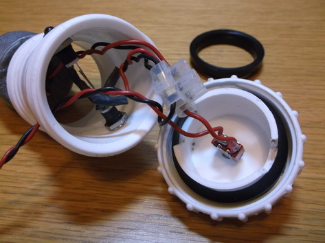
The LED lamp, side looking LED's and the on/off switch are connected together with a piece of 3-way terminal block.
The side looking LED's and the series resistor are connected across the 12V supply. The LED terminals and the resistor are enclosed withing heat shrink sleeving.
The rear panel where the switch is mounted had to be modified slightly cutting two slots so that the rear panel does not foul on the side looking LED's. The slots were cut using a sharp craft knife. The slots are visible either side of the switch body.
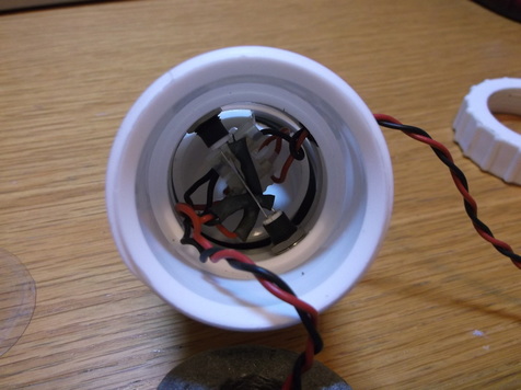
This picture shows the internal mounting of the components a little more clearly, particularly the 'side looking' LED's.
The LED's are mounted in bezel's that are screw mounted on the main light body. It took a while to locate a source of these parts that had a plastic body and at a reasonable cost. The chrome ones would possibly rust when exposed to extreme weather. I have experimented with plastic LED clips but these did not seem to hold the LED in place as firmly as i would have liked. In the very first prototype i used a small piece of wood jammed between the two bodies of the LED's to hold them firmly in the mounting holes!
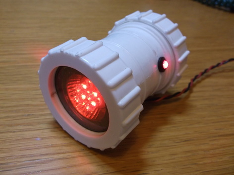
Here the 12V/0.6W light is being bench tested to demonstrate it in operation. The plastic red filter works very well giving a good even light output.
