Background
I travel a lot due to my work commitments and find using a laptop on planes, in hotels, while out and about can often by quite uncomfortable due to the poor lighting which makes using the keyboard quite difficult. I decided to try to create a simple light that could be used to illuminate the keyboard and could be powered from the laptop. I came up with this implementation. It uses standard 12V/1.5W LED bulbs driven from a step up voltage converter that steps up the 5V to the 12V required to drive the LED. The driver circuit is based around the PIC 12F675 microprocessor and software developed in another project for items like this. The hardware and software emulate the operation of the Texas Instruments TI497 switch mode power supply chip in the step up mode. The software developed to drive the converter circuit was written in a mixture of 'C' and assembler developed using the Microchip MPLABX IDE tool. Assembly language was used to generate accurate times for the pulse width generation part of the circuit.
The circuit and light are mounted in an acrylic tube with walls that are 3mm thick providing great rigidity and robustness. The light is powered from the 5V supply available from a USB plug so it can be powered from a laptop, phone charger, car USB socket etc. The lamp can be used as a general purpose torch in the car or house as it can also be powered from a battery power bank, in fact any USB power source.
The circuit and light are mounted in an acrylic tube with walls that are 3mm thick providing great rigidity and robustness. The light is powered from the 5V supply available from a USB plug so it can be powered from a laptop, phone charger, car USB socket etc. The lamp can be used as a general purpose torch in the car or house as it can also be powered from a battery power bank, in fact any USB power source.
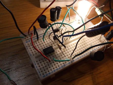
This photograph shows the components used to make this project assembled on a breadboard to test and verify its operation. There are a few extra components such as low value resistors which were used to sense the current in parts of the circuit to verify the value and wave forms.
The extra components will not be used in the final implementation.
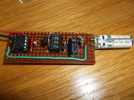
In this picture, the prototype circuit has been constructed on copper strip board. This was cut to size before starting construction.
The components had to be positioned somewhat unconventionally as the vertical space is limited inside the acrylic tube.
The completed board was connected to a 5V power supply and tested for a few hours. The voltages and wave forms were also checked with an oscilloscope.
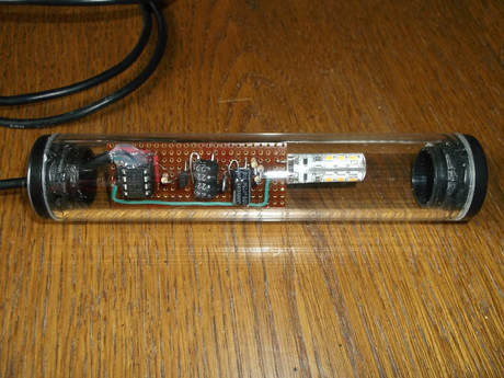
A piece of acrylic tube was cut to house the LED bulb and drive circuit.
A USB cable was modified to allow the power wires to be soldered to the driver board.
One of the end caps was drilled to allow the USB cable to enter the tube.
Hot weld glue was used to secure the wires powering the driver board to its surface and also to secure the cable where it passes through the end cap.
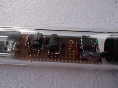
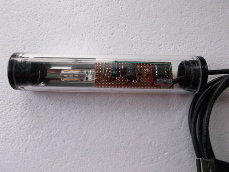
This picture shows a close up detail of the driver board mounted inside the acrylic tube.
It also shows the hot weld glue protecting the power connections to the driver board.
Some silvered plastic film was cut to size and inserted into the acrylic tube to act as a reflector so that the light output would be reflected in one direction
This photograph shows the completed USB light/torch unit.
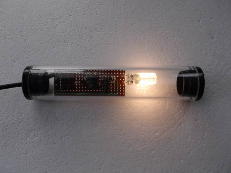
This photograph shows the USB Light/torch unit powered from a USB connector.
