Background
I live in a block of flats that has communal stair lighting in the stairwells. The lighting was maintained by the local council until about 2016/2017 when they handed responsibility for its maintenance to the residents with little or no notice! The maintenance has consisted of replacing the fluorescent tubes and starters when required until recently. At least one of the units had the bulb and starter replaced but did not work.
One unit outside my flat was removed and i investigated the possibility of repairs.
When the local Council handed over responsibility for maintenance to the residents i took some time to collect information on how the system worked and the gathered information on the components. This became particularly useful when i started to look into repairs and or upgrades to LED units.
The stair lighting is controlled by a 365 day timer which has a dial that was designed for our specific longitude and latitude ensuring that the lights go on and off at dusk. It is an electro-mechanical timeclock system and has been in use for over 40 years. Each light unit has two fluorescent tubes in it on separate circuits. At dusk both fluorescent tubes are switched on and at approximately 01:00hrs one tube in each light unit is switched off to save energy and which also has the side effect of hopefully extending its operating life
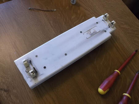 Fluorescent light fitting removed from housing, lamps removed.
The light fittings were manufactured in Glasgow by Coughtrie, a company which still exists and still supplies the same types if lights.
Based on the manufacturing dates on the components the units were made around 1979/1980.
The units are very solid and clearly designed for the kind of rouch treatment they may get, and there is evidence that they did over many years.
This picture shows the base plate with both tubes removed.
The tube holders, sometimes referred to as 'tombstones' can be seen at both ends. The base plate has two pins at its bottom end where it can be pivoted down to access the components on the rear.
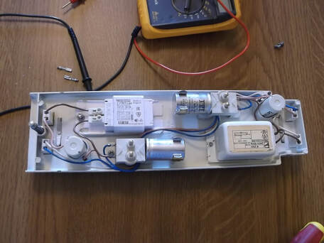
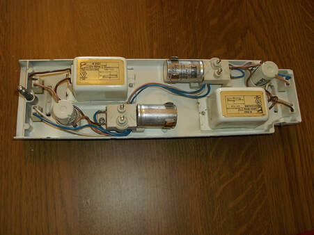 Fluorescent lamp fitting, rear showing components and wiring.
The units are completely modular and all connections are by 4mm spade/push-fit connectors meaning that all components are replaceable or in todays parlance 'plug-n-play'. There are two independent circuits with separate wiring which are controlled by the time clock.
Taking this picture and using the lower set of components as a guide:
At the immediate left is one of the fluorescent tube connectors, next to the right of it is the starter unit, next is the two spring loaded prong unit which connects to the manes in the base of the light unit. This contains a built in replaceable 3 Amp fuse. The capacitor, intended to provide Power Factor correction and suppress switching transients plugs into this unit. This is followed by the Ballast(large white box) and finally at the right and side is the second tube connector.
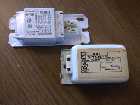 Old & New Ballast shown side by side.
When the tube and starter unit were replaced in this light unit it did not fix the problem, the light did not start. I examined all the wiring and found it all seemed to be ok. i checked that the capacitor had not gone open circuit and it was ok. finally i checked the ballast( basically an inductor, long piece of wire wrapped around an iron core) and found it had gone open circuit. I compared this against the other ballast in the same unit which was known to work and found it was ok. The ballasts are sealed and potted with resin so there was no way of repairing them. After a bit of research on the internet i found that there were two ways to go:
1. find a compatible magnetic ballast which would be a fairly straight forward replacement or...
2. find al electronic ballast that would be a bit more efficient but would require a lot more work to rewire into the unit.
It had to be accepted that given the age of the unit, greater than 40 years direct replacement parts would be difficult if not impossible to obtain. This picture shows the replacement unit at the top compared to the failed unit at the bottom. I ordered this replacement magnetic ballast online together with a compatible electronic one. I plan to use the electronic ballast in some experiments as magnetic ballasts are expected to become more difficult to get in the coming years as they are being phased out in favour of the electronic ones.
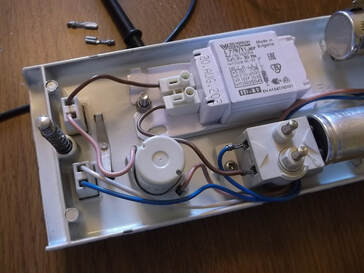 New ballast fitted and wired in place.
The magnetic ballast purchased was actually a good bit larger than the suppliers website indicated however it was possible to safely fit it in.
The original mounting hole had to be slightly enlarged and the ballast was secured in place with a stainless steel M5 bolt and locking nut.
The spade/push-fit connectors were removed from the wire and the insulation stripped to allow the wire to be connected to the ballast via its spring terminals.
 Repaired light fitting showing new and old Ballasts fitted and all wiring installed.
This picture shows the completed unit with the new ballast installed.
The original starters and Fluorescent tubes were re-installed to see if they worked... using the Reduce-Reuse-Recycle motto, why throw away something that was still working?
The base unit was refitted to the lamp unit in the stair and successfully tested, both lamp units worked as expected.
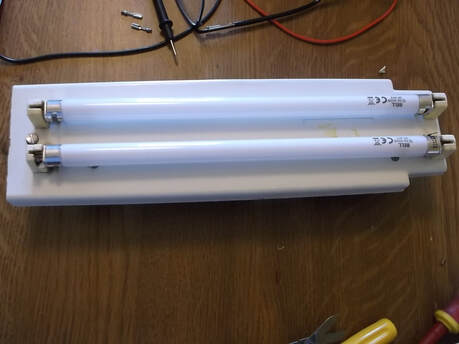 Repaired light fitting cleaned up with Fluorescent tubes re-fitted.
This picture shows the base plate cleaned up removing the years of grime and with the two original fluorescent tubes installed and ready to be tested in the base unit.
The fluorescent tubes are T5 units, 300mm 240V/8Watt.
Now that this approach to the repairs has been shown to work it will be tested for a few months to see that it is a reliable solution and then rolled out to the other units if they exhibit the same problems.
Hopefully with this approach the expense of replacing the entire stair lighting system can be delayed for a number of years until LED lighting has been proven to be as reliable and maintainable as the fluorescent ones have, of course that all depends on the continued availability of T5 fluorescent tubes.
