Background
I use a Linksys / Cisco RV042 router as part of my home/office network set up. Unfortunately it recently failed and tripped the 12V power supply.
I left the router powered off for a few hours and then powered it on again. It started to power up then reset a couple of times and then refused to boot up.
I have seen this happen a number of times before with other equipment such as DVD players, LCD TV power supplies etc. After checking the power supply output was ok, i turned my suspicions to the power supply capacitors inside the router which may have failed, so i opened up the case to investigate further.
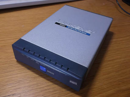
The RV042 is a good value for money router that i have used for a number of years now. It replaced a 3Com Office Connect router.
The RV042 provides IPSEC, PPTP and a proprietary IPSEC based 'QuickVPN' so that i have a choice of VPN options while travelling to contact home.
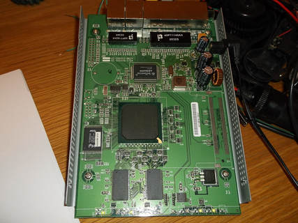
The case was fairly easy to open requiring the removal of one screw and then separating the two halves of the case and removing the front and back plastic bezels.
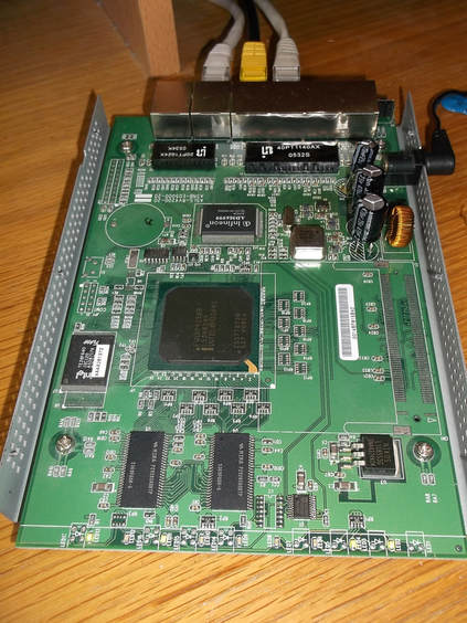
The only circuit board occupies the entire case and is secured with 4 screws. The PCB has a fairly small number of components. There are three electrolytic capacitors on the circuit board, 1 x 220uF/25V and 2 x 1000uF/25V.
The 220uF capacitor is connected across the 12V supply. The 2 x 1000uF capacitors are connected across the 3.3V output generated by a three terminal adjustable regulator on the PCB. Rather than try to figure out which of the capacitors had failed i decided to replace all three.
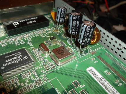
The capacitors were quite difficult to de-solder with a 25W soldering iron due to the amount of copper on both sides of the circuit board acting as a heat sink.
This large amount of copper is also used as part of the design to dissipate the heat generated by the internal components without having to use heatsinks or forced cooling.
Great care had to be taken to minimise damage to the circuit board through plated holes while de-soldering and removing the components. The component mounting holes were a very tight fit for the capacitor leads.
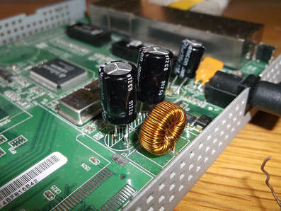
Due to the very tight fit of the components, i decided to mount the replacement capacitors above the board and ensure that the through plated holes were filled with solder to connect both sides of the board rather than try to force the leads through the holes.
It is an unorthodox method but as the router is not subjected to large shock loads the capacitor mounting leads will not come under stress.
In this picture the new capcitors have been installed, the board powered up and the system tested while connected to PC's etc on the network.
The board was 'open case' tested for several hours to verify the system operation.
The voltage input and the 3.3V on board regulator output was measured periodically to verify the stability.
During this time it was noticeable how much heat was dissipated by all the components. The PCB and all the components were uniformly warm confirming the theory that the PCB copper is part of the heat dissipation design. I was concerned at how warm the new electrolytic capacitors were, but this will be due to the electrical leads transmitting the heat from the PCB up into their metal bodies.
I have rigged up some external cooling using a fan to ensure the temperature does not get excessive.
After a couple of days under test the case was re-assembled and re-installed into my network set up.
