Background
My neighbours outside light stopped working a few weeks ago. I assumed the problem was a blown bulb, however when it was replaced the light still did not work. Rather than try to locate the fault while up a ladder in freezing cold weather i removed the light from the wall and tested it on a work bench.
The external casing paint had corroded over the years but other than that the light was still in good condition. When i dismantled the lamp i was shocked to find that some components were mounted beneath a mains filter capacitor. This is most definately not good manufacturing practice nor is it in my opinion a safe practice. The lamp is supplied to a number of large DIY chains in the UK.
The external casing paint had corroded over the years but other than that the light was still in good condition. When i dismantled the lamp i was shocked to find that some components were mounted beneath a mains filter capacitor. This is most definately not good manufacturing practice nor is it in my opinion a safe practice. The lamp is supplied to a number of large DIY chains in the UK.
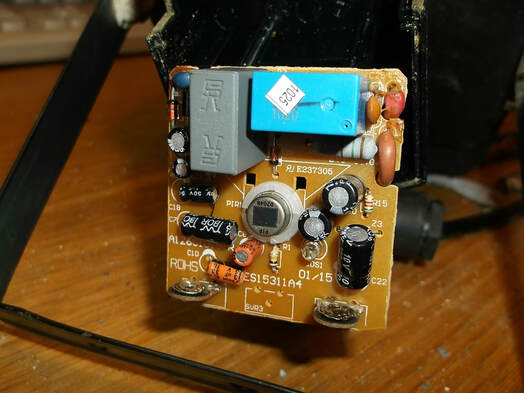
The main control circuit board is shown here. The PIR motion sensor is mounted in the centre of the board. The light detector which controls the light level at which the unit operates is just above the '01/15' label on the PCB and looks much like a 3mm LED.
The two skeleton potentiometers that control the on-time and operating light level are mounted at the bottom edge of the circuit board.
The bulb is connected to and from the mains voltage by a relay, the blue component at the top right of the PCB.
The circuit board was in good condition with little or no signs of water or dust contamination showing that the weatherproof box was doing its job.
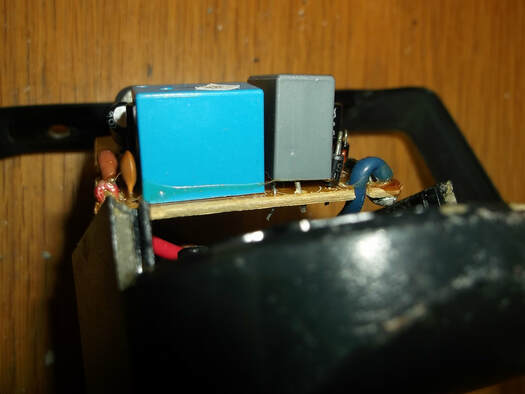
This picture shows what at first was a badly mounted component, namely the mains capacitor(grey box component.)
On closer examination i found that the reason the component was not lying flush to the circuit board was because two components were mounted beneath it, very close to mains voltages.
This is most definitely not a good manufacturing nor operating practice.
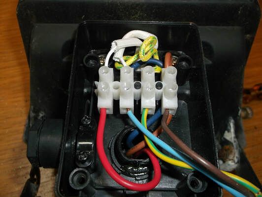
This picture shows the electrical connecting block that connects the mains input to the control PCB and the bulb.
I found that some of the connections had come loose which would explain why the light was not operating correctly.
The light had been using a 400 Watt bulb which when bench testing generated a phenomenal amount of heat, very dangerous to be working beside in fact. That and the extreme cold of winter could easily cause expansion and contraction to loosen poorly tightened electrical connections.
I removed all the connecting wires, cleaned them up and reassembled them. The 400 Watt bulb was replaced by a more appropriate 120 Watt Halogen bulb which will reduce energy consumption and light the appropriate area rather than the whole garden.
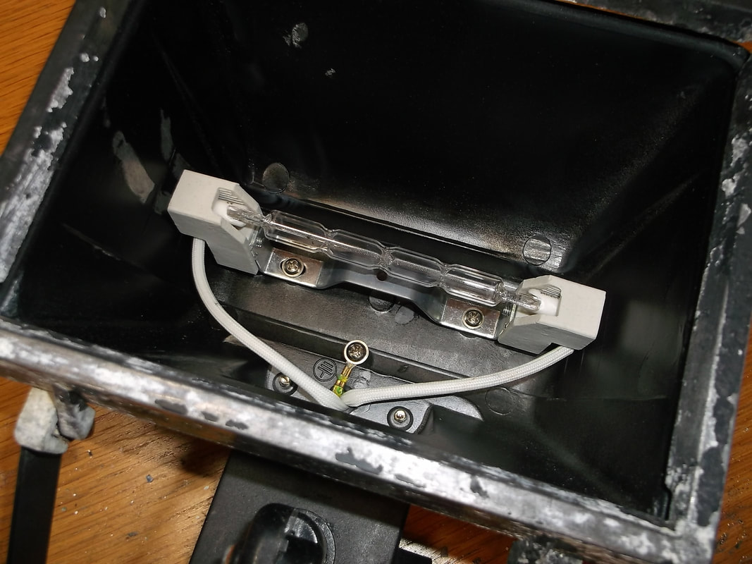
While the lamp was dismantled the rear foil reflector was removed and cleaned. This also allowed the wires and bulb contacts and connections to be inspected and cleaned.
The lamp was reassembled and tested for a couple of days to correctly set the operating light level and the on-time.
The lamp was then remounted on the wall and tested in its operating position. The 13 amp fuse that had been installed in the fused switch unit inside the house was replaced with a much more appropriate 5 Amp device.
With a couple of hours work including testing a light that is getting on for 10 years old should give many more years of service rather than ending up in landfill or left at the back of a shed.
