Background : Tubular Rear Light
For a number of years 'bar' type LED rear bike lights have been popular. I decided that i would implement my own version using high brightness LED's and a PIC to generate various light patterns. The light has to be light weight, operate from around 5V or lower and be easily transportable.
Below is the outline of the solution that was developed.
Below is the outline of the solution that was developed.
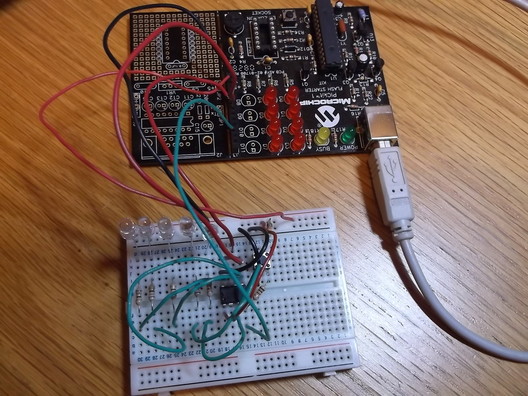 Prototype breadboard circuit and PICKit1 Development Board.
A basic simple circuit was designed using 5 high brightness LED's, a switch and a Microchip PIC 12F675 in an 8 pin DIL package.
The 12F675 was chosen as a number of other projects have been developed using it so a it was readily to hand, it has up to 6 configurable input/output pins and has only 8 pins so can be packaged into small areas.
Of the 6 I/O pins, one is used as an input for the light pattern selector switch and the remaining 5 I/O pins are used to drive the LED's.
A prototype circuit was developed on breadboard and the PIC 12F675 was programmed using a PicKit1 development board.
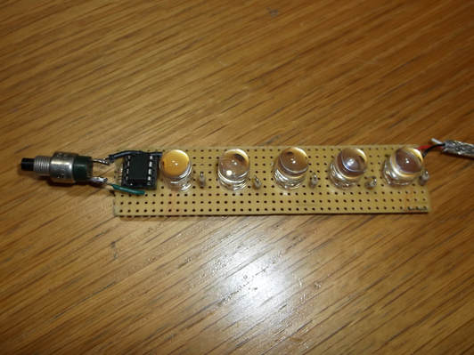 Prototype Rear LED light on strip board.
After the prototype circuit was constructed the software was developed using the Microchip MPLABX IDE.
The program was written in C using the Microchip XC8 compiler.
After the software was developed and debugged the prototype circuit was constructed on single sided copper strip board.
The layout of the circuit board and its dimensions were controlled by the dimensions of the acrylic tube to be used to house the circuit board.
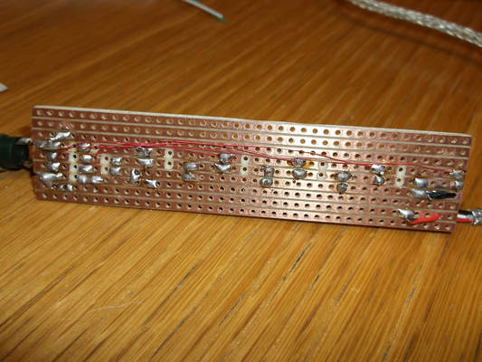 Strip board solder side showing enameled wire connections.
To make the construction simpler, rather than use wire connecting links on the component side enameled copper wire was used to make the connections on the solder side of the board.
This was achieved using a homemade wiring pen which i had not used for almost 30 years. For more details about the wiring pen refer to the photographs and text below.
When all the wiring was completed the enameled copper wires were held in place with a few drops of hot weld glue along their length.
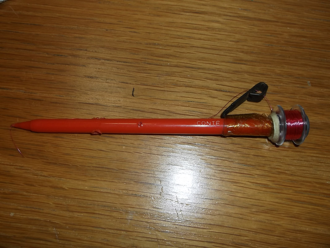
There was a circuit prototyping system made a number of years ago by 'Vero' which used enameled copper wire to make connections between circuit components. It was similar to wire wrapping but did not use the special component sockets. The connections were made by wrapping the fine wire around component leads and the soldering would melt off the enamel from the wire. If i remember correctly the pen was sold under the name 'Veropen'. Various accessories were also available such as pin number labels and plastic combs to guide wires around IC's.
|
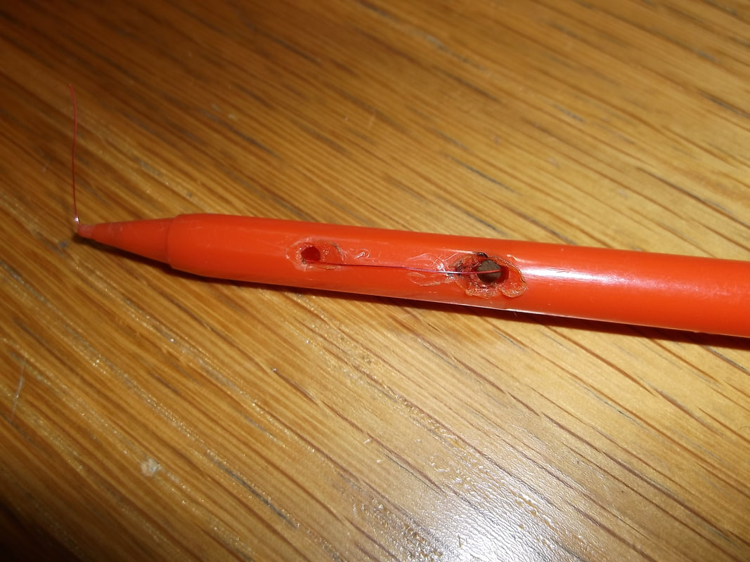
A university lecturer came up with this home made version constructed from a a plastic propeller/ejector pen with the internal mechanism removed. A few holes are burned into the plastic(or can be drilled) and the wire is fed through the holes and out where the pencil lead would have been. The wire bobbin is secured in place with a screw and a few washers to allow it to rotate easily. The wire is smoothly spooled off the reel via a brass picture hook secured to the side of the pen. The user places a finger over the wire on the outer surface and then feeds out the wire wrapping it around the component leads.
|
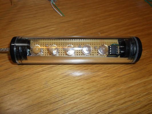 Completed prototype installed in Acrylic tube.
The circuit was mounted in a piece if acrylic tubing with plastic push fit end caps.
Suitable sized holes were drilled in the end caps for the light pattern selector switch and the power supply cable.
The power cable was made from a recycled USB cable using only the power wires.
The power cable was secured in place with some hot weld glue on both the circuit board and where it passed through the plastic end cap.
Some metallised plastic film was cut and inserted into the acrylic tube to reflect and direct the light output.
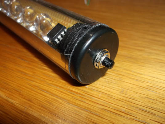 Light pattern selector switch.
This picture shows one of the end caps with the light pattern selector switch installed.
The switch is soldered to the PCB with stiff wires and secured to the end cap with a lock washer and nut.
Together these secure the PCB inside the acrylic tube.
The PIC 'remembers' the light pattern last selected in the PIC 12F675 on chip EEPROM so that it does not have to be re-selected each time the light is switched on.
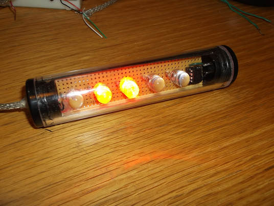 Completed LED bar light under test.
This photograph shows the finished light in operation displaying one of the light patterns.
The light was tested outside in a dark street and is easily visible well beyond 200m with all light patterns.
The PIC 12F675 can operate down to 2.5V. This means that the maximum capacity of the batteries can be used. The light was tested with fully charged batteries running them down until the pack was producing 2.6V at the terminals while operating the light. The light output was still very good and the patterns were still able to be selected. The running time of the batteries was greater than 40 hours continuously.
