Background
I live in a building that has an entryphone system. The panel at the front door to the building has lighting built in to help visitors read the name labels at night. The lighting is supplied by 2 x12V MES incandescent bulbs. Unfortunately these tend to burn out and as they are on 24 hours even the long life versions which claim up to 5000 hours will only last 6 to 7 months. As the system has been installed for over 25 years this represents a lot of bulbs and a lot effort removing and reattaching the front panel. I decided to develop a LED based system which in theory would have a minimum life of 25,000 hours, roughly 34 months assuming that the LED's were driven with a current of 30mA. If the current is reduced the life would be extended beyond 34months. The LED version would in theory have a life of almost 6 times the incandescent version.
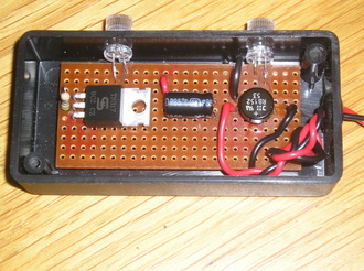
The secret to ensuring long life of high power LED's is to drive them with a constant current source. The circuit shown is fed with a 12V AC supply which drives a circuit consisting of a bridge rectifier, a smoothing capacitor, an LM317 voltage regulator and resistor configured as a constant current source. The circuit drives two ultra-bright LED's in series, but the circuit and PCB layout were designed to allow a third LED if the entryphone panel needed it.
The 12V AC supply was already present as part of the entryphone system.
The 12V AC supply was already present as part of the entryphone system.
I estimated that four LED's would be required to light the entryphone system and the light needed to be spread as evenly as possible inside the entryphone panel hence two control units would be required.
I tried to use what ever components i had to hand so one unit uses 4 discrete diodes to produce a full wave bridge rectifier while the other unit uses a bridge rectifier module.
Similarly one unit uses protruding fresnel LED lenses to mount the LED's into the side of the case while the other uses 5mm rubber grommets.
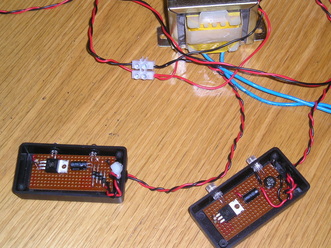
Both units were bench tested on a 12V AC power supply generated from a mains transformer i had to hand. The units were tested for 72 hours. The temperature of the LM317's were measured to ensure they stayed well within limits. The TO220 version was used as this has greater tolerance to heat than the TO9 version and can dissipate heat more efficiently.
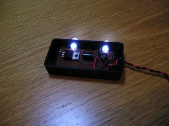
This photograph demonstrates the light output of one of the units which uses the protruding fresnel lenses to distribute the light.
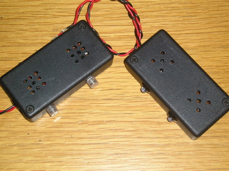
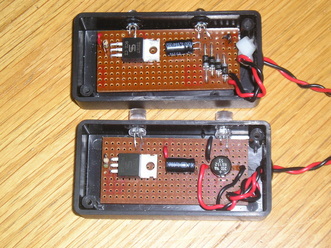
Both versions of the completed light units are shown here ready to be installed in the entryphone panel at the front door. Ventilation holes were drilled in each case to allow efficient air flow. Although the power dissipation of the LM317 in this circuit could only be up to 200mW(worst case) the entryphone system faces south and is in the direct line of the sun for most of the day so the ambient temperature inside the panel can easily get to 30C-35C on very hot days.
The units were fixed to the rear of the entryphone panel using double sided 'sticky dots' to allow mounting and removal as easily as possible as the inside of the panel is quite congested with buttons, mounting brackets and wires.
The units were fixed to the rear of the entryphone panel using double sided 'sticky dots' to allow mounting and removal as easily as possible as the inside of the panel is quite congested with buttons, mounting brackets and wires.
As of April 2014 the LED lighting units have been in operation for 30 months( approx. 21500 hours) and there have been no problems. The light output is still as good as the day the unit was first installed.
