Background
For a number of years i have been using 12V LED bulbs(GU5.3) for bike lights , propagator grow lights , hand held torches and other lighting projects. On a bike a small 1.2AHr sealed lead-acid battery is not too inconvenient but for portable lights such as hand held torches it is not quite so convenient. An alternative is to use 10 x 1.2V Ni-Cd or Ni-MH AA or AAA size batteries but it can be difficult to conveniently package these to make them portable. I had supplied lights to a good many people who were delighted with the results but when it came to the bike lights i was always asked the question..."..is it possible to run them from a lower voltage more convenient power source."
While i personally find a small SLA battery not inconvenient or too heavy on my bike others did not have the same view. An SLA requires a special charger which added to the number of chargers everyone had to keep, phone, iPad, iPhone, AA/AAA battery chargers etc.
Running bike lights from 10 x AA/AAA batteries is quite feasible but packaging these can be a little inconvenient but most of all most domestic chargers can only charge 4 AA/AAA batteries at a time so charging 10 batteries requires a bit of organization and discipline.
I already have a 6V (4.5Ahr) SMART lighting system on my bike which runs a 2.4Watt and 10Watt twin light system. I have had this since about 1998 and since developing the 12V LED lights i had stopped using the 6V system. However with the desire to drive the LED's from a lower voltage system i could see an opportunity to rationalize all the lighting and electrics on my bike.
I set about designing a circuit that would drive the 12V LED's from 4 x AA/AAA. Strange as it may seem i rejected the idea of using a DC-DC converter primarily because of the size of the smoothing capacitors required on the output stage. They would be very difficult to package in a small housing on handle bars or in a hand held torch. Instead i decided to use a circuit based on a switch mode constant current drive system. The circuit is self oscillating and supplies high frequency pulses of current to the LED lamp. The results so far have been very good with the circuit being easily adaptable to drive LED bulbs from 0.6Watt to 7.5Watt giving excellent light output.
The circuit can also be powered from a 6V SLA battery allowing it to be powered from the same battery driving the current SMART lights meaning that all the lighting could be powered from one source. As the 6V SLA battery has a capacity of 4.5Ahr it would not need to be recharged frequently.
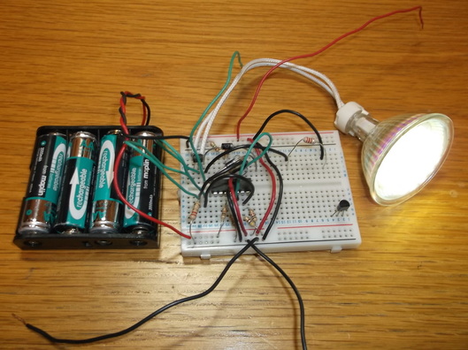 Breadboard prototype driver circuit driving 12V 1.6Watt LED.
The circuit was developed on a piece of breadboard using easily available low cost components. The heart of the circuit is a LM339 open collector output quad comparator. This senses the current in the output circuit comparing it against the reference level and switching the output on and off as required.
In this picture the circuit is driving a 1.6Watt LED made from 38 discrete white LED's. I purchased a number of these while on business in Spain about 4 years ago as they were much cheaper there than here in the UK.
The circuit is powered by 4 x 1.2V Ni-MH AA batteries.
The inductor used to generate the drive voltage is a 220uH axial device which can be seen at the top right hand corner of the breadboard. The 1.6W power output is the largest that this particular device could handle.
As the picture shows, the LED gives a very bright high level output.
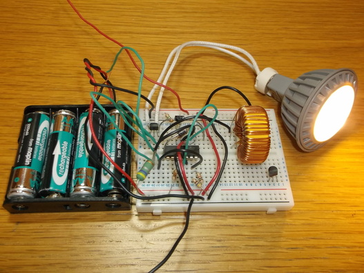 Breadboard prototype driver circuit driving 12V 4Watt 3 LED bulb.
In this picture the circuit is driving a 4Watt LED made from 3 high power LED's.
The current sensing resistor seen at the bottom left of the breadboard has been changed to handle the higher current of the LED bulb.
The circuit used here to drive the 4W LED is identical to the one driving the 1.6W LED apart from the inductor and current sensing resistor.
The inductor has also been changed to a 220uH device rated at 1A as the LED sinks approximately 450mA, much too high for the axial devices. Unfortunately this inductor is physically quite large but it was the only one available at the time. I hope to source a smaller device in future. The 4W LED bulb was replaced with 5W and 7.5W LED bulbs and this circuit gave excellent performance with no further component changes although the values have been calculated to drive these devices.
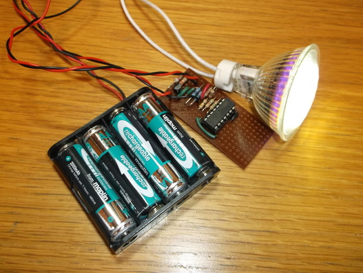 PCB/Strip board prototype driver circuit driving 12V 2.3Watt LED bulb.
The breadboard circuit was transferred to a strip board layout and constructed to be tested on my bike and as a hand held torch.
In this picture the circuit is driving a 1.6W LED bulb consisting of 38 LED's powered by 4 x 1.2V AA batteries.
The space on the circuit board was left vacant when first constructed. It is intended to house the components that will drive two discrete LED's in my bike lights. The two LED's are sideways looking and intended to improve my visibility to other road users at road junctions.
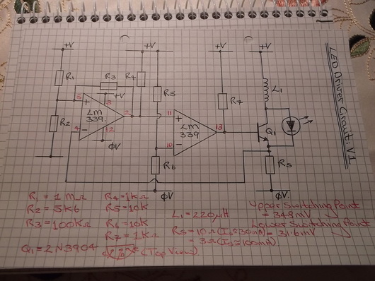
This is the circuit that was used to develop this LED driver.
The sense resistor, Rs can be changed for different power LED's.
