Background : Philips Car Radio Refurbishment

My Dad had got this car radio around 1975/1976 through a relative who worked in the Electrical/Electronics Domestic goods trade. It was quite unusual for the time as it was a removable unit, i.e. the body of the radio could be removed from the car and used as a standalone portable or table top radio when it was fitted with internal AA batteries.
Unfortunately this type of removable unit was necessary in the 1970's and early 1980's because car radio theft was so common and there was a healthy second hand trade in stolen units.
This particular unit was fitted to an Austin Morris 1300, a Morris Marina 1.3 Coupe and finally to a Ford Fiesta. I remember spending most of a weekend fitting it to the Austin Morris 1300 and having to cut a slot in the metal fascia/dashboard although there was huge satisfaction listening to the distant MW and LW stations on the first evening when it was completed.
The Morris Marina and Ford Fiesta were both fitted with a small floor mounted centre console(the same one) and the radio was mounted into that. It was so much easier than cutting the fascia.
The radio was removed from the Ford Fiesta in 1985 when it was sold and put into storage in the shed. I recently came across it while clearing out the shed. I thought it would make a good project to refurbish it and see if i could get it going again.
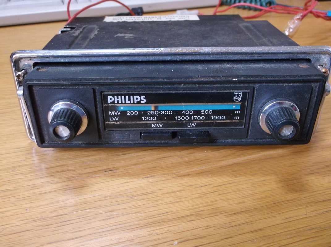
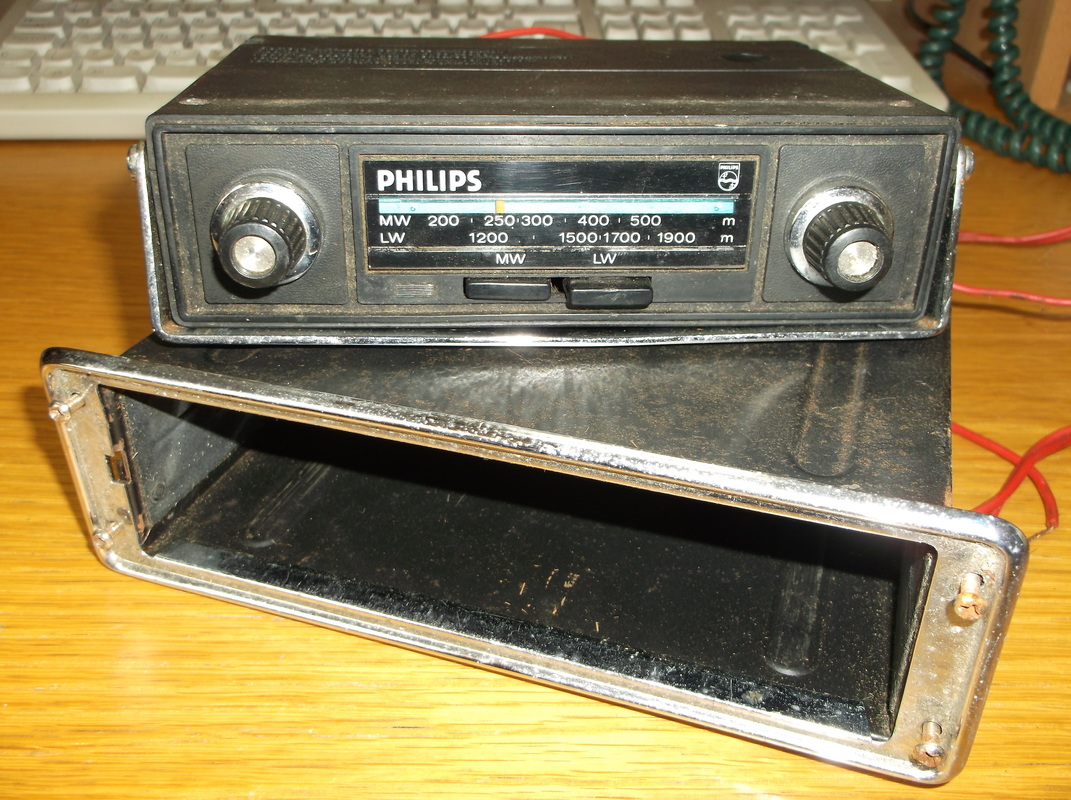
This shows the complete radio unit mounted in the outer housing. There was a small long 'key' which was used to unlock the radio from the outer housing. There was a slot at the left side of the radio where the key was inserted.
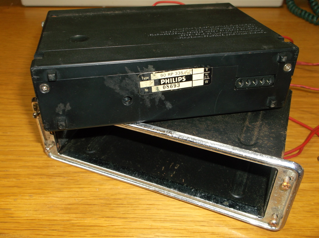
This shows the rear of the radio with the unit removed from the outer housing. The socket unit(with 5 plugs) at the right hand side of the rear of the unit can be seen here This connects with a set of pins inside the outer housing and connects the aerial, external speaker and power supply to the radio when it is installed in the outer housing.
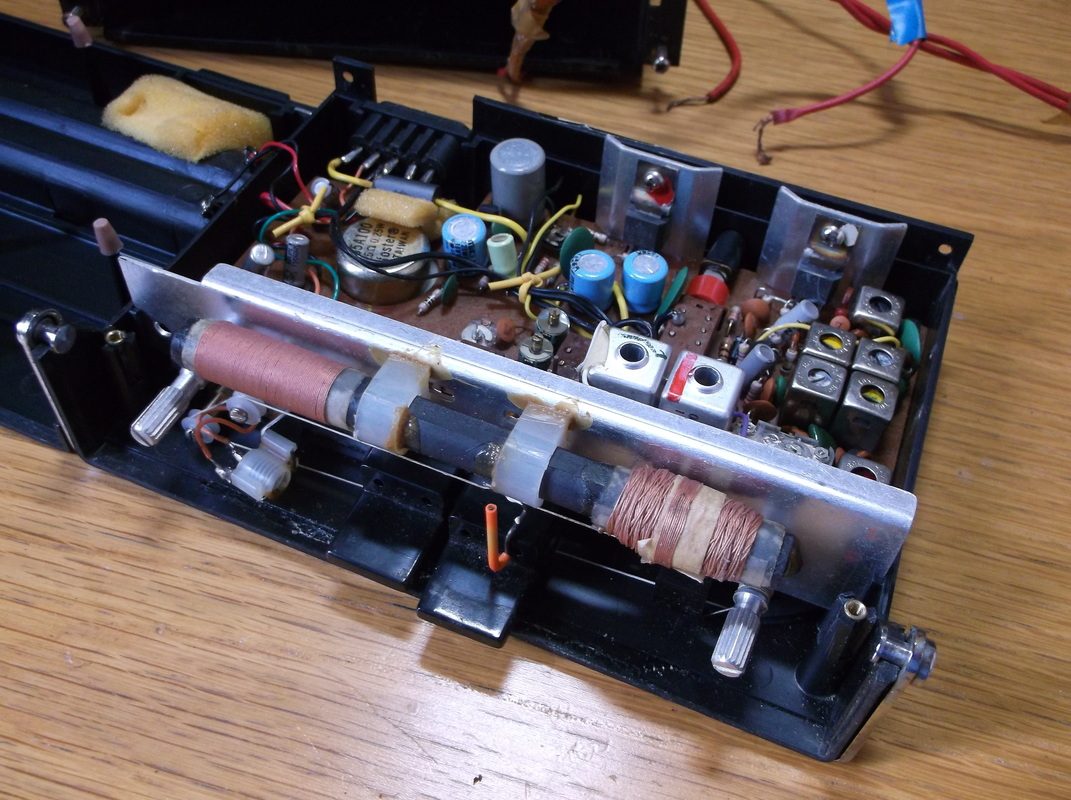
Here the top casing and front panel have been removed from the radio. Internally the radio is in good condition with very little dirt or dust other than around the edges of the case. There is no sign of component damage or failure. The internal ferrite rod aerial with the LW and MW coils is clearly visible in the foreground.
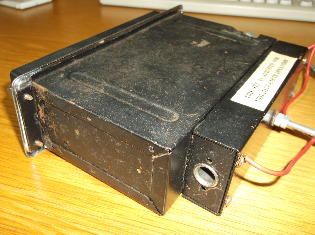
Here the outer housing is shown with the car aerial socket in the foreground. Although the case shows some surface rust it is otherwise in good condition and should clean up well.
|
This shows the radio removed from the outer housing. The metal work is a little grubby and shows signs of surface rust but other than that it was in good condition.
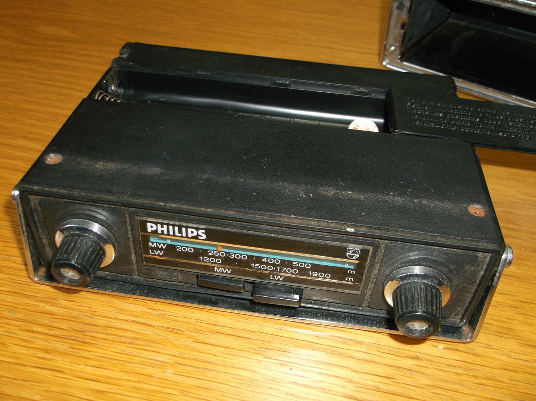
Here the radio is shown outside the outer housing with the battery cover removed. The radio is powered by 6 x AA batteries in standalone mode.
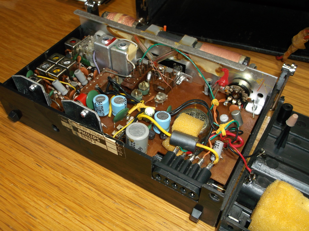
This shows a rear view of the internal components with the top case removed. The internal components are all fairly standard for the time.
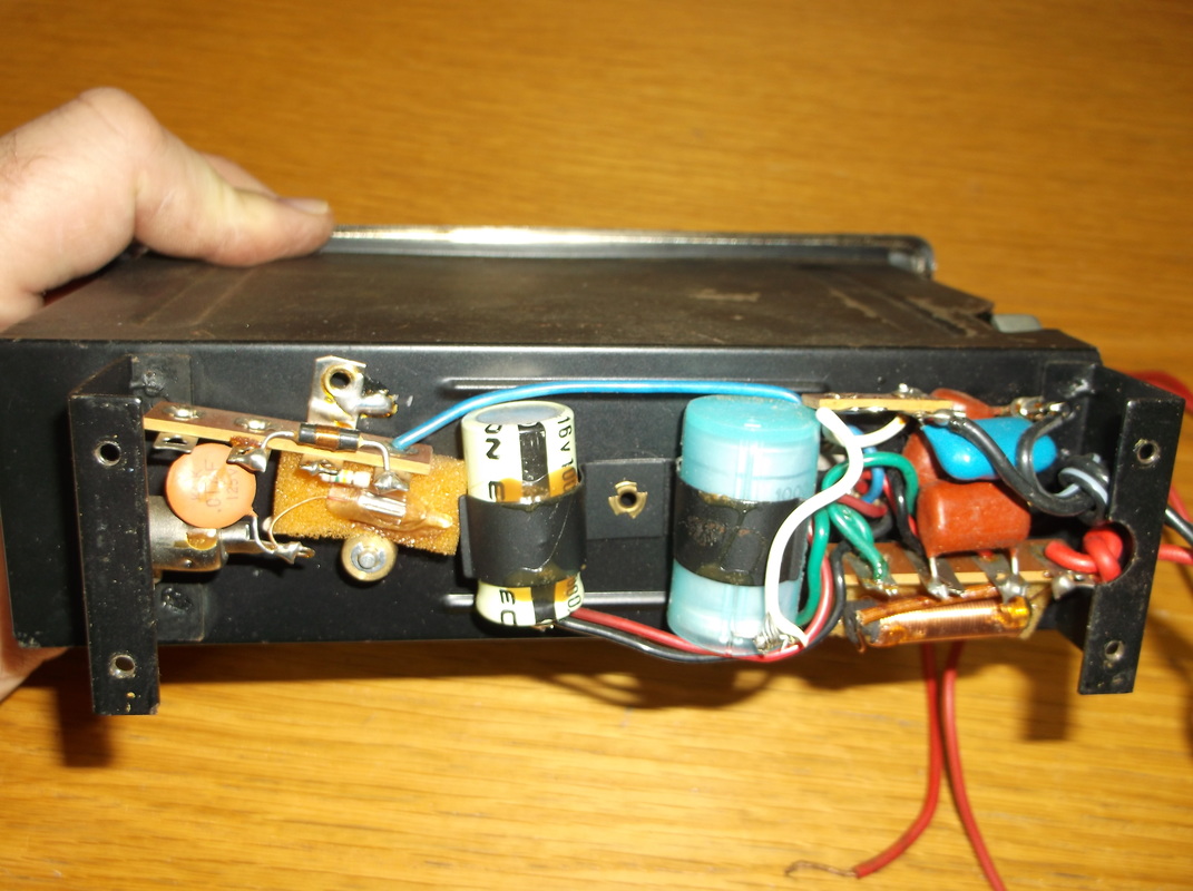
In this picture the rear cover has been removed to show the internal components of the outer housing. Most of the components are to provide filtering to the power supply and the aerial input signal.
|
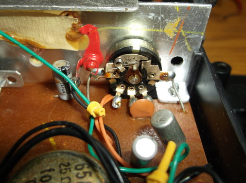
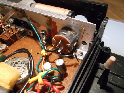
This picture shows the rear of the on/off/volume switch.
Unfortunately while testing the radio i found that the volume control is very erratic and generates a lot of noise when the control knob is rotated. This usually indicates that the internal carbon track of the potentiometer has failed and the entire unit will have to be replaced. It should be fairly easy to replace although the exact style and construction may be different on more modern units.
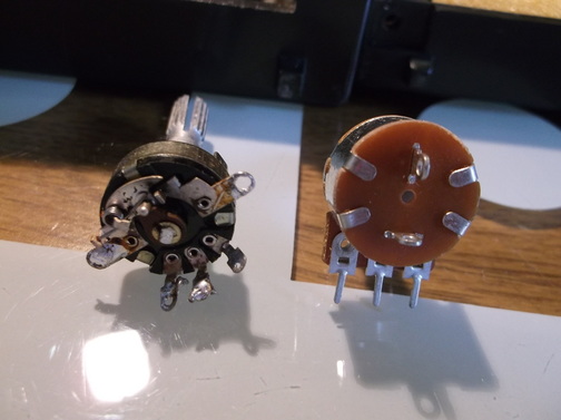
This photograph shows the old volume control removed from the radio next to the new one.
I found it very difficult to get one of identical construction so i opted for a compatible part.
The shaft length on the replacement volume control was shorter than the original however the plastic shafts on the control knobs are long enough to compensate for this.
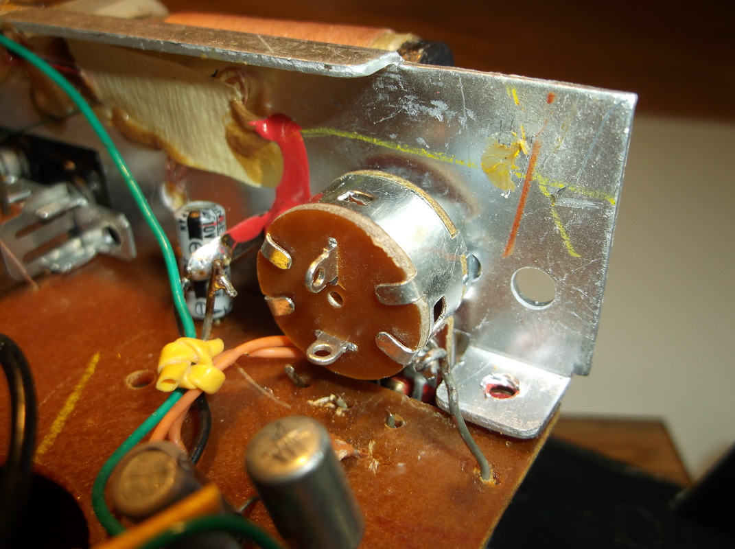
The damaged volume control was removed from the radio. The potentiometer contacts were de-soldered as were the on/off switch contacts. The new device was of a slightly different construction with different contact layout. To get the device fitted to the front panel the the screws securing the PCB to the front panel were removed. This allowed the front panel to be moved allowing the contacts to be fitted into the slot in the PCB.
|
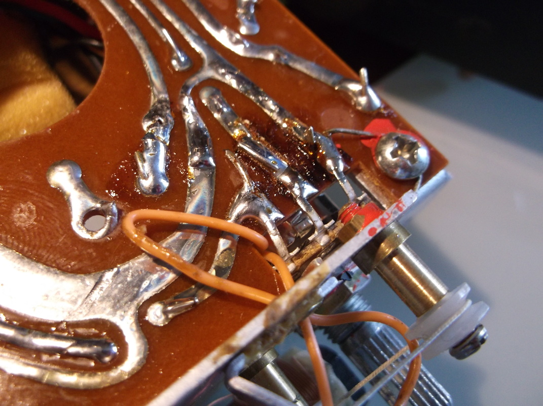
The potentiometer shaft was secured in place with the shaft nut. The screws securing the PCB to the front panel were re-installed. The potentiometer contacts were carefully bent over into contact with the solder pads and then soldered to the PCB.
|
On the rear of the new device the on/off contacts were connected to the original flying leads on the PCB using insulated extension flying leads.
Solid wire flying leads were used as these would be less susceptible to breaking due to vibration in the event the radio were to be installed in a vehicle again.
The radio was tested by installing 6xAA batteries. The radio powered up and the volume control was now smooth with no crackling or interference when it was adjusted.
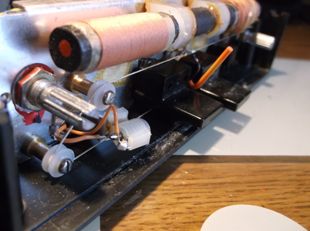
The next job was to replace the on/off-backlight on the front panel. The bulb holder can be seen just below the volume control shaft. The bulb was not present and i do remember the light working in the 1970's and i also have a vague memory of removing it to get a replacement but obviously never got round to it! I decided to upgrade the back light with a green LED rather than a miniature incandescent bulb.
|
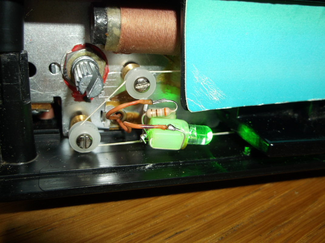
I planned to use the original bulb holder to mount the LED. The bulb holder was removed from the front panel, the connections de-soldered and the metal contacts carefully removed from the plastic housing. The led pins were inserted into the slots where the contacts had been. A 390 Ohm current limiting resistor was soldered to the LED anode and the positive supply lead was soldered to the other end of the resistor.
|
The cathode of the LED was soldered to the negative supply lead.
The exposed leads around the current limiting resistor were enclosed in a piece of heat shrink sleeve to prevent possible contact with the surrounding metalwork which is connected to the negative battery supply.
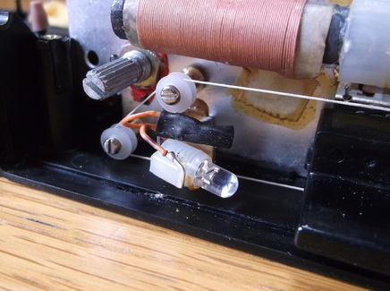
The completed LED/resistor assembly was then re-mounted onto its bracket on the front panel.
The radio was then partially re-assembled, inserted into its case and connected to a 12V supply to verify that the LED was working correctly.
The radio was then completely re-assembled and installed into the mounting case.
A converted PC power supply was used as a 12V source for the radio.
A length of wire was used as an aerial connected to the rear aerial socket.(The internal MW/LW aerial does not work particularly well as it is enclosed in a metal box when the radio is mounted in the case.)
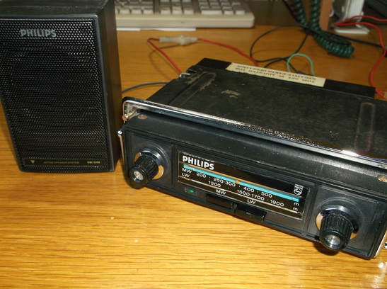
An external speaker was attached which happened to be from a pair of Philips speakers intended for personal cassettes or CD players purchased around 1993.
The radio performed very well and in this picture the dim glow of the green LED on/off light can just be seen. In a darkened room the LED gives a very satisfying green 'glow' back lighting to the tuning display reminding me of the times spent in the 1970's and early 1980's trying to tune into distant foreign stations on dark evenings while out in the car.
Now that the electrical repairs have been completed and the plastic casings cleaned up only the refurbishment of the casing, possibly some repainting and polishing of chrome work needs to be completed.
More to follow soon.....
Planned work to refurbish unit.
1. Cleanup and repair paintwork and chrome where required.
2. Repair front grill of unit
3. Repair or replace on/off/volume control. - completed.
4. Repair/replace internal tuning panel back light bulb. - completed.
Planned work to refurbish unit.
1. Cleanup and repair paintwork and chrome where required.
2. Repair front grill of unit
3. Repair or replace on/off/volume control. - completed.
4. Repair/replace internal tuning panel back light bulb. - completed.
